
 De
De  Es
Es  Fr
Fr  Pt
Pt 

-
-
-
-
-
-
-
-
-
-
-
-
-
-
-
-
-
-
-
-
-
-
-
-
-
-
-
-
-
-
-
-
-
-
-
-
-
-
-
-
-
-
-
-
-
-
-
-
-
Design of pipelines for internal and external cone
-
-
-
-
-
-
-
-
-
-
-
-
-
-
-
-
Design of pipelines for internal and external cone
 Library: Pipe fittings.
For example:
Pipe fittings - Connections on External Cone - GOST 139xx-74 - Pipes
Pipe fittings - Connections on Internal Cone - GOST 160xx-70 - Pipes
...
Two ways to build a pipe path
First - automatic connection of two pipe fittings elements.
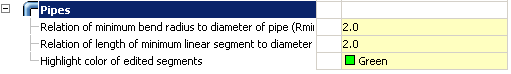
When joining the program selects the shortest distance: pipe length is calculated from the minimum values of the linear section and minimum bending radius of the pipe diameter.
The parameters are set in the pipeline nanoCAD Mechanica (team Settings).
To automatically connect the two valve elements specify the connecting member (bushings, elbows, tees, crosses), hold down SHIFT. nanoCAD Mechanica generate trajectory tubes and displays the dialog box with the geometric size of the segment of the pipeline. If the proposed path will not suit you, it can be edited in the same window.
Second - step by step construction of the pipeline with a consistent set the direction and length of the pipe segment.
Step task trajectory pipe begins with the first element of the valve. The insertion point and pipe diameter are determined automatically.
Next, follow the prompts on the command line, you can create the path of the pipeline, consistently introducing straight and arched portions.
For automatic connection of the pipe end to an element of reinforcement necessary to open the context menu.
Select option C bonds and provide an element of reinforcement with which to make the connection.
Call the following context menu again by pressing the right mouse button.
Select it as the pipe sections need render.
The compound can be performed in three or five sections.
By clicking the right mouse button to complete the command.