
 De
De  Es
Es  Fr
Fr  Pt
Pt 

-
-
-
-
-
-
-
-
-
-
-
-
-
-
-
-
-
-
-
-
-
-
-
-
-
-
-
-
-
-
-
-
-
-
-
-
-
-
-
-
-
-
-
-
-
-
-
-
-
Design details of rotation
-
-
-
-
-
-
-
-
-
-
-
-
-
-
-
-
-
Design details of rotation
 Main menu: Mechanical - Design >
 Create shaft.
Ribbon: Mechanical - Design >Create shaft.
Toolbar: Create shaft ( "Design").
 Command line: MCARBOR.
Basic rules
After invoking the command, pick an insertion point.
Set the shaft direction by moving the mouse.
Left clicking creates a shaft segment.The command remains active and allows additional segment to be drawn.
nanoCAD Mechanica auto-detects the insertion point of a graphic element which is to be inserted, and acquires its geometry from a standard database.The auto-dected elements are highlighted in color.After the insertion command has been invoked, elements are highlighted at the mouse movements.Left-click to confirm.
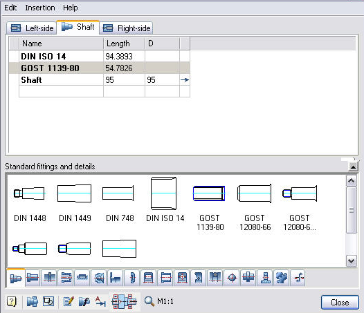
Dialog box Editg shaft

|
Show / Hide section Standard fittings and details sections |

|
Add element |

|
Insert Group |

|
Edit Object |

|
Insert design |

|
Add view / section |

|
Scale of details and shaft sections |
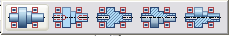 Shaft section displays methods
Composition tab "Standard fittings and details" is defined folder structure in the system folder "shafts" Database nanoCAD Mechanica.
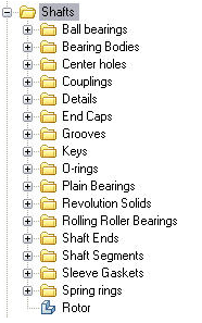
In addition, in the tabs of the Edit shaft dialog are included
- Tooth-wheels
- Efforts
- User folders
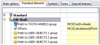
Path to these elements are specified in the option nanoCAD Mechanica (Standard Elements >Edit shaft ).