
 De
De  Es
Es  Fr
Fr  Pt
Pt 

-
-
-
-
-
-
-
-
-
-
-
-
-
-
-
-
-
-
-
-
-
-
-
-
-
-
-
-
-
-
-
-
-
-
-
-
-
-
-
-
-
-
-
-
-
-
-
-
-
-
Cylindrical Gearing Strength Analysis
-
-
-
-
-
-
-
-
-
-
-
-
-
-
-
Cylindrical Gearing Strength Analysis
 Library: Calculations - Spur gears - Cylindrical Gearing Strength Analysis
In what follows the parameters and characteristics related to the gear, given the index 1; relating to the wheel - the index 2.
The initial data are encouraged to use:
-
typical transmission loading mode (GOST, features 32, p.106.) or load sequence diagram (GOST, features 14, p. 63);
-
the torque on the shaft of the wheel gear - T2, N * m (if the load is variable, then how current torque accepted most of long-acting);
-
Wheel speed - n2, min. - 1;
-
the gear ratio gear set - u;
-
the type of gears (spur, helical, herringbone);
- tooth angle -
 ;
; -
offset coefficients source generating circuit - x1 and x2;
-
transmission type: reversible or irreversible. By reversing or non-reversing gear transfer meant a two-way or one-way load application;
-
term transmission service - Lh, h;
-
material and a method of chemical-thermal hardening of gear wheels and transmission calculated;
-
the location of the calculated gear in the drive according to the scheme in accordance with GOST, p. 58, fig. 13a.
Enter the initial data for the design of the transmission by means of the dialog box, shown in figure:
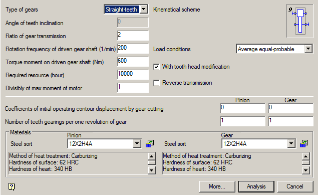
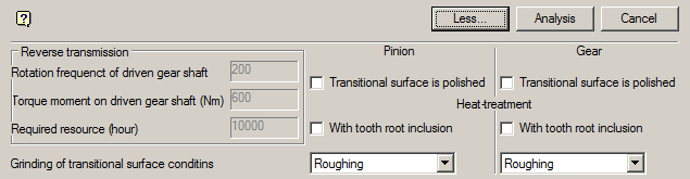
By clicking on the button "More ..." open additional field data input for the reverse gear, the method of machining the tooth flank and its heat treatment.
Initial data
Type of gears
The drop-down list of the gear types allows you to select one of three options: spur, helical, herringbone or wheel:

Angle of teeth inclination
When choosing a helical or herringbone wheels in the "angle of the teeth" should enter a value in degrees of the desired angle of inclination of the tooth line in the recommended range (typically 8-22 ° for helical and 25-40 ° for chevron wheels).
If this field is left blank, the program installs by default a certain angle, which lies within the specified limits. Most often, this angle imposed by the previous calculation. It can be changed either directly or by subsequent adjustment calculation.
Ratio of gear transmission
The field is filled in accordance with the terms of reference and the expected characteristics of the engine.
Rotation frequency of driven gear shaft (1/min)
The field is filled in accordance with the terms of reference and the expected characteristics of the engine.
Torque moment of driven gear shaft (Nm)
The field is filled in accordance with the terms of reference and the expected characteristics of the engine.
Required resource (hour)
The field is filled in accordance with the terms of reference and the expected characteristics of the engine.
Divisibly of max moment of motor
The field is filled in accordance with the terms of reference and the expected characteristics of the engine.
Kinematical scheme
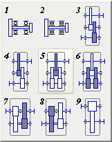
Click on the field with the image of the kinematic scheme reveals nine schemes of gear reducers, from which you can choose the layout of the gear pair corresponding to the estimated case. Estimate the case highlighted in white.
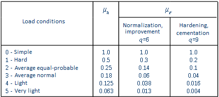
Load conditions
Load conditions is selected from the dropdown list.
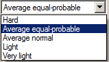
Table of values of equivalence ratios for each loading mode:
Check "With tooth head modification"
Check "Reverce transmission"
It makes active group of source data "" Reverse transmission ".
Koefficients of initial operating contour displacement by gear cutting
Number of teeth gearings per one revolution of gear
Group "Materials"
Materials of gears and their characteristics are selected from a drop down list or from the database.
 Go to the database by clicking on the appropriate button to the right of the selection grade of steel.
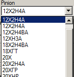
Type of material selection group gears and wheels:
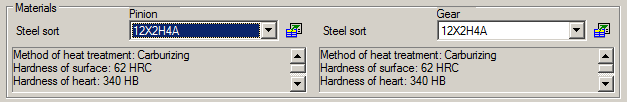
For convenience, you can select to see comments to the selected material.
Group "Reverce transmission"
The group contains the following fields:
- Rotation frequenct of driven gear shaft
- Torque moment of driven gear shaft (Nm)
- Required resource (hour)
Check "Transitional surface is polished"
Check "With tooth root inclusion"
Grinding of transitional surface conditins
Activity fields depends on the chosen material
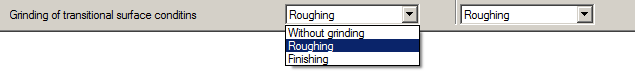
If the transition is made grinding surface of the teeth, the required grinding mode can be selected from the corresponding drop-down list.