

 De
De  Es
Es  Fr
Fr  Pt
Pt 

-
-
-
-
-
-
-
-
-
-
-
-
Customize User Interface
-
-
-
-
-
-
-
-
-
-
-
-
-
-
-
-
-
-
-
-
-
-
-
-
-
-
-
-
-
-
-
-
-
-
-
-
-
-
-
-
Customize User Interface
 Ribbon: Manage – Customization – Interface >
  Customize interface
Menu: Tools – Customize > Interface…
 Command line: INTERFACE
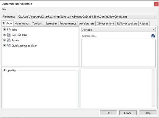
Customize User Interface dialog box is intended to:
· create and edit ribbon elements (tabs, context tabs, groups and icons);
· create new menus, toolbars, context menus;
· fill menus and toolbars by commands and create new commands;
· edit the composition and parameters of interface objects;
· add and change actions on objects, accelerators, aliases, tooltips;
· save all changes in a separate .cfg file and manage configuration files.
|
|
Attention |
|
All changes made to the Customize User Interface dialog enter into effect after the program is reloaded. |

|
|
Attention |
|
When making changes to the interface settings through the Customize User Interface dialog, the display and location settings for palettes and toolbars are reset to the state specified by the user in the Customize User Interface dialog. |
|
|
Note |
|
Transferring and copying interface settings can be done using the UIIMPORT and UIEXPORT commands. |

Dialog options
File
Drop-down menu with commands to manage configuration files:
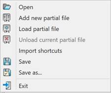
 Open – opens the dialog for searching and opening a configuration file with the *.cfg extension.
 Add new partial file – creates a custom partial configuration file.
 Load partial file – connects a partial configuration file to the main configuration file (master file).
 Unload current partial file – disconnects the current partial configuration file.
Import shortcuts – loads keyboard shortcuts (combinations of hot keys for quick opening nanoCAD commands).
 Save – saves the current configuration file.
 Save as… – saves the current configuration file under a different name.
 Exit – exits the dialog.
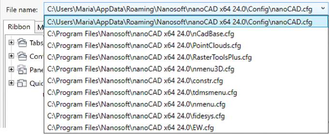
File name
A drop-down list of all configuration files, the field displays the path and name of the edited cfg file. The created user interface elements are added to the selected file. By default, the current configuration file is opened.
|
|
Note |
|
The contents of the connected partial configuration files are displayed when you select the cfg file to which they are connected. Interface elements are changed/deleted in the file to which these objects belong, regardless of which file is currently selected. |
Tabs
The dialog contains 9 tabs: Ribbon, Main menus, Toolbars, Popup menus, Accelerators, Object actions, Status bar, Rollover tooltips, Aliases
Parameters
|
File name |
Field displays the path and name of edited CFG-file. |
|
File
|
Commands to manage config files: · Open · Load partial file · Upload current partial file · Save · Save as… · Clear · Exit |
Upper left part of dialog displays all elements of opened tab. Move selected element with drag&drop.
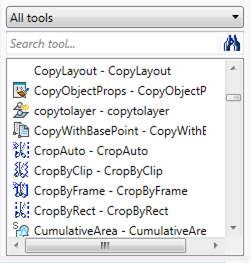
Upper right part of dialog contains all nanoCAD tools: commands and controls. Use them to create and edit interface objects: menus, toolbars, status bar.
There is a filter for tools:
· Select a section to display elements of selected category.
· Or type the template to find appropriated tools
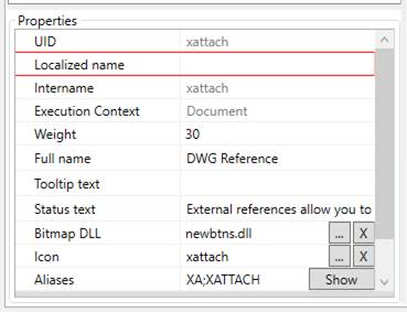
Information about the selected element and action to be done with it is displayed in the right bottom corner of the dialog box.
Properties in the lower left part of dialog displays properties of selected elements; they can be edited.
Commands for creating and editing interface elements (menus, toolbars, status bar, etc.) are called from the context menu of the element. The composition of the context menu commands depends on the current dialog tab and the selected element.
Work with partial configuration file
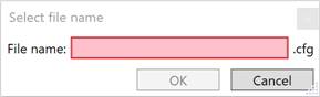
1. Select the Add new partial file command in the menu of the File button of the Customize User Interface dialog.
2. In the Select File Name dialog that opens, enter the file name. Click OK.The created files located in C:\Users\User_name\AppData\Roaming\Nanosoft AS\nanoCAD x64 26.0\Config.
3. Select the created file from the drop-down list in the File name field. The tabs of the new configuration file are empty.
4. Create user interface elements (menus, toolbars, status bars, etc.).
5. Save the partial configuration file using the Save command in the File button menu.
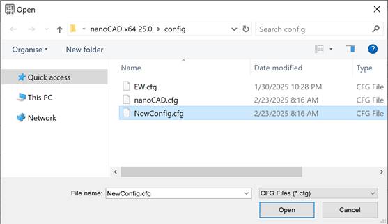
6. Connect the partial configuration file using the Load partial file command in the File button menu. In the Open dialog box that opens, select the created partial configuration file.
7. Click OK in the Customize User Interface dialog.
8. Restart nanoCAD. The user elements are displayed in the interface.
9. To disable a partial configuration file, select the file in the drop-down list in the File name field and then select the Unload current partial file command in the File button menu.
When manually editing the configuration file, you can include additional files using the line #include <FileName.cfg>. If the file to be included is located in another directory, you should write the full path to it.
The process of creating a custom menu, toolbar and ribbon with examples is described in the article “Creating a custom menu, toolbar and ribbon in nanoCAD”, located on the official Nanosoft AS development website.