

 De
De  Es
Es  Fr
Fr  Pt
Pt 

Creating a hatch
 Main menu: Mechanical - Utilities >
 Create hatch.
Toolbar: Utilities >Create hatch.
 Command line: MCHPATTERN.
In nanoCAD Mechanica it is possible to create hatches according to a given pattern - a sketch using the
"Create hatch" tool. The hatch pattern created with it is written as an independent * .pat file and can be used in other projects or by other users.
Procedure
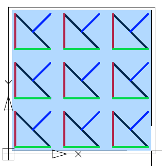
1.Create a border for the hatch sketch. Construct a 300x300mm rectangle and place its bottom-left corner at the origin of coordinate system 0,0,0. The sketch area must be at the origin of the coordinate system. Overall dimensions of the sketch area should not be more than 300x300mm.
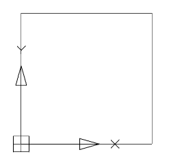
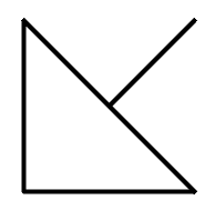
2. Sketch one element of the future hatch. The sketch needs to be done within the created rectangle. The sketch should only be done with lines. It is not allowed to sketch with arcs, circles. It is recommended to approximate curved objects in polylines without arc segments. Sketch polylines must be exploded into line segments.
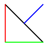
3. Assign a different color to each section of the sketch. The sketch should be done with segments of different colors. The hatch tool recognizes the periodicity in the sketch by the color of the lines.
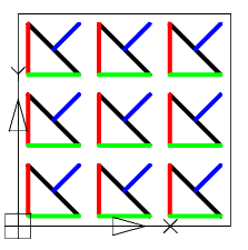
4. Create an array of sketches within a rectangle. The sketch must follow an explicit periodicity. The sketch must include at least three repeating fragments of the future hatching.
5. Call the command "Create hatch".
6. Create an array of sketches within a rectangle. The sketch must follow an explicit periodicity. The sketch must include at least three repeating fragments of the future hatching.
7. Press the "Enter" key. The process of object recognition and analysis will begin. During recognition, gaps in sketch lines are automatically determined, if in the selected pattern the line break is outside the selection boundary, the line will be defined in the hatch as continuous. If the sketch does not meet the conditions, a message box will appear, otherwise the file save dialog.
8. Correct the errors indicated in the message. Repeat step 5 - step 7.
9. In the file save dialog specify the path to the hatch file.
| Important! | You cannot use the names "Acad.pat", "Acadiso.pat" as the name of the sample file. It is recommended to save in C:\ProgramData\Nanosoft\nanoCAD Mechanica 25\SHX |
10. The custom hatch will be created. The hatch created with the "Create hatch" tool fully accepts all the properties of the
nanoCAD hatch: associativity, the ability to change the scale, the angle of inclination, overlay with a closed tolerance.
| Important! | A drawing file * .dwg that used a unique hatch must be transferred to another user along with the * .pat file of the hatch pattern. For a successful translation, use the (eTransmit) "Generate Set" command. |