De
De  Es
Es  Fr
Fr  Pt
Pt 

-
-
-
-
-
-
-
-
-
-
-
-
-
-
-
-
-
-
-
-
-
-
-
-
-
-
-
-
-
-
-
-
-
-
-
-
-
-
-
-
-
-
-
-
-
-
-
-
-
-
-
-
-
-
-
-
-
-
-
-
-
-
-
-
-
-
-
-
-
Construction note
-
-
-
-
-
-
-
-
-
-
Construction note
 Main menu: Draw - Notes >
 Construction note.
Main menu: Construction - Notes >Construction note.
Ribbon: Annotate - Leaders >Construction note.
Ribbon: Construction - Symbols >Construction note.
Toolbar: Notes >Construction note.
 Command line: SPNOTEP, NOTEP.
Procedure
1. Call the command "Construction note".
2. If "Show dialog before inserting the object" is active, the "Construction Note" dialog opens. In the "Construction Note" dialog box, enter text and define the leader options. Click the "OK" button.
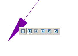
3. Pick a point on the object (select the object) to which the leader arrow will point. To select an object, use the "Select" context menu command; to freely specify a point in the drawing, use the "Free" context menu command.
4. Place the leader shelf in the drawing.
| Note: |
If the parameter "Angle step of extension line" is arbitrary, it is possible to place the leader ledge orthogonally in the ORTO mode (F8). When you turn on the ORTO mode via the "SHIFT" key, Object Snap (F3) must be turned on. |
5. If the "Show dialog before inserting the object" option is disabled, the "Construction Note" dialog will open. In the "Construction Note" dialog box, enter text and define the leader options. Click the "OK" button.
6. The note is built.
Menu
-
 Multi-line text - the switch controls the display of multi-line text on the shelf;
 -
 Frame - text under the shelf is framed;
 - Type arrows:
-
 None,
None, -
 Arrow,
 -
 Point,
 -
 Open arrow,
 -
 Half-arrow,
 -
 Oblique;
 - Align text horizontally:
-
 By left edge,
 -
 By center,
 -
 By right edge;
 -
 Insert special symbol - the command allows you to insert a special character into the input field;
 -
 Notebook - the command allows you to insert data from a notebook into the field;
 -
 Match properties - command copies appearance parameters from another object;
 -
 Add extension line - the command allows you to add an additional note line;
 -
 Global options - note settings.
Context menu
The context menu opens in the input field. View Context menu entry fields.
Fields
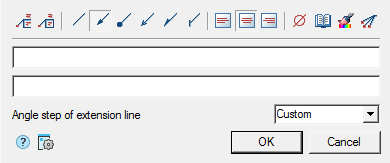
The default positional leader contains two input lines and a list for specifying the pitch of the bevel angle.
The first line is for the label above the leader shelf, the second is under the leader shelf.
In the "Angle step of extension line" list box, the slope angle of the leader lines is selected:
- Custom - a leader line is placed arbitrarily (default);
- step 15° - the leader line is put down with a step multiple 15°;
- step 30° - the leader line is put down with a step multiple 30°;
- step 45° - the leader line is put down with a step multiple 45°;
- step 90° - the leader line is put down with a step multiple 90°.
Arrow type selection context menu
When you call the context menu on the note arrow (without selecting the note), a dialog box for selecting the arrow type will appear.