
 De
De  Es
Es  Fr
Fr  Pt
Pt 

-
-
-
-
-
-
-
-
-
-
-
-
-
-
-
-
-
-
-
-
-
-
-
-
-
-
-
-
-
-
-
-
-
-
-
-
-
-
-
-
-
-
-
-
-
-
Common settings
-
-
-
-
-
-
-
-
-
-
-
-
-
-
-
-
-
-
-
-
Common settings
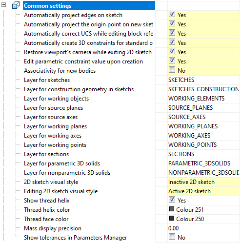
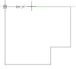
Automatically project edges on sketch
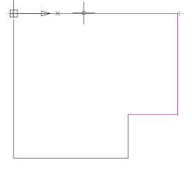
The parameter when adding a new sketch adjusts the display of the projection of the edges of a flat face taken as the working plane for the sketch.
Call command "Add planar sketch".
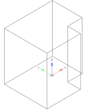
Specify a flat face as a work plane.
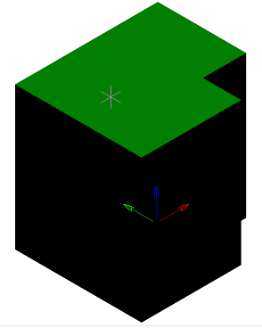
Depending on the setting, a projection will be added to the sketch.
| Yes | No |
|---|---|
|
|
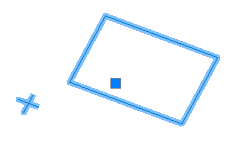
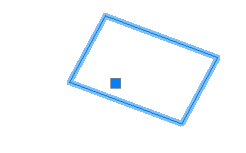
Automatically project the origin point on new sketch
Controls the projection of the origin point when creating a new sketch.
| Yes | No |
|---|---|
|
|
Automatically correct UCS while editing block references with 2D constraints
Automatic correction of UCS when editing a block reference with 2D constraints.
Automatically create 3D constraints for standard objects
Automatically create 3D constraints when inserting standard objects into parts and assemblies.
Restory viewport's camera while exiting 2D sketch editing mode
If enabled, the view camera will be in position before the sketch is edited.
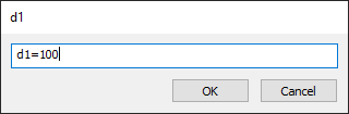
Edit parametric constraint value upon creation
Controls whether the dependency editing dialog is opened immediately after installation.
Associativity for new bodies
The enabled option allows you to build fixed bodies without the possibility of defixation. The sketch must be attached to some plane.
Layer for sketches
It allows you to customize the name of the layer on which will be placed flat sketches.
Layer for construction geometry in sketchs
Allows you to customize the name of the layer on which the design primitives will be located.
Layer for working objects
It allows you to customize the name of the layer on which the objects will be located.
Layer for source planes
Allows you to customize the name of the layer on which the source GCS planes will be located.
Layer for source axis
Allows you to customize the name of the layer on which the source GCS axis will be located.
Layer for working planes
Allows you to customize the name of the layer on which the created work planes will be located.
Layer for working axis
Allows you to customize the name of the layer on which the created work axis will be located.
Layer for working points
Allows you to customize the name of the layer on which the created work points will be located.
Layer for sections
It allows you to customize the name of the layer on which section will be located.
Layer for parametric 3D solids
Allows you to set the name of the layer on which the parametric 3D bodies will be located.
Layer for nonparametric 3D solids
Allows you to customize the name of the layer on which non-parametric 3D parts will be located.
2D sketch visual style
Visual style of 2D sketch primitives.
Editing 2D sketch visual style
Visual style of 2D sketch primitives during editing.
Show thread helix
Controls the display of the thread helix.
Thread helix color
Thread helix color.
Thread face color
Thread face color.
Mass display accuracy
Mass display accuracy for inspector properties and part and assembly unit properties.
Show tolerances in Parameters Manager
Mass display tolerances in Parameters Manager and properties of parts and assemblies.