
 De
De  Es
Es  Fr
Fr  Pt
Pt 

-
-
-
-
-
-
-
-
-
-
-
-
-
-
-
-
-
-
-
-
-
-
-
-
-
-
-
-
-
-
-
-
-
-
-
-
-
-
-
-
-
-
-
-
-
-
-
-
Change hidden mode
-
-
-
-
-
-
-
-
-
-
-
-
-
-
-
-
-
Change hidden mode
 Main menu: Mechanical - Standard parts- Cover >
 Change hidden mode.
Toolbar: "Standard parts">Change hidden mode.
 Command line: MCCHCOVER.
The command switches the display mode of hidden lines.
nanoCAD Mechanica allows you to hide individual graphics elements. The overlapping nature of the base object or user block is determined by a special parameter - the overlap level ZOrder. ZOrder - this is a numeric parameter whose value determines the overlap priority. An object with a large ZOrder value overrides an object with a lower value.
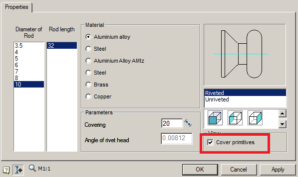
Primitives nanoCAD have the lowest overlapping level and therefore are always overlapped by objects from the database. That at an insertion of object nanoCAD Mechanica objects nanoCAD did not overlap, it is necessary to disable the switch in the object insert dialog "Cover primitives":
The area in the drawing that the base object covers nanoCAD Mechanica, is called "Contour of suppression". An overlap exists within this contour.
Procedure
-
Call command.
-
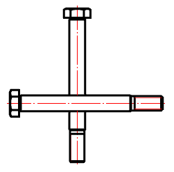
In the context menu, select the desired view of the overlapped objects "Normal", "Dotted" or "Switch".
Normal Dotted Switch
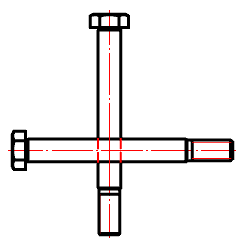
The command appends the value. Those. If a normal overlap has been established, then the dashed line becomes, and vice versa. -
Select the secant frame for the objects for which you want to change the overlapping mode.
-
Repeat if necessary items 2 and 3, or complete the command on the key "Enter".