

 De
De  Es
Es  Fr
Fr  Pt
Pt 

-
-
-
-
-
-
-
-
-
-
-
-
-
-
-
-
-
-
-
-
-
-
-
-
-
Chamfer
-
-
-
-
-
-
-
-
-
-
-
-
-
-
-
-
-
-
-
-
-
-
-
-
-
-
Chamfer
 Ribbon: Home, Draw - Modify >
  Chamfer
Menu: Modify – Chamfer…
Toolbar: Modify –
 Command line: CHA, CHAMFER, MCHAMFER
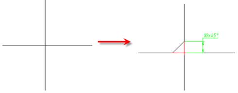
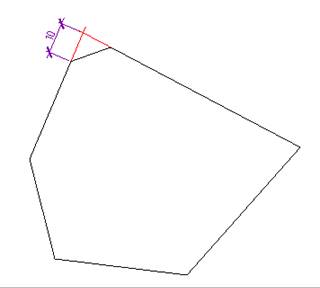
This command is used for automatic and semi-automatic placement of chamfers on parts with different designs and with automatic dimensioning ability. The command allows the creation of several chamfers individually.
The command works with both linear objects (line, polyline) and non-linear ones (arc, ellipse, circle, spline).
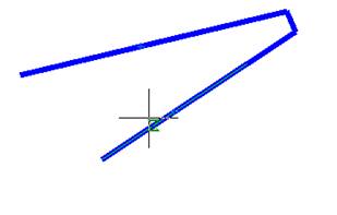
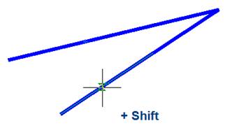
The Chamfer command can be used for quick trimming or lengthening of selected objects. To do so, press the SHIFT button when you select objects: a current value of chamfer radius is temporarily changed to 0 and objects are lengthened or trimmed to intersection point.
After launching the command, the dialog box for specifying the chamfer parameters opens:
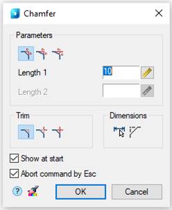
Parameters:
|
|
This button switches on the mode for creating a chamfer with similar lengths. In this mode the Length 2 parameter is unavailable.
|
||
|
|
This button switches on the mode for creating a chamfer with different lengths.
|
||
|
|
This button switches on the mode for creating a chamfer by length and angle. In this mode there is a Corner parameter instead of the Length 2 parameter.
|
||
|
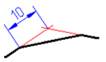
Length 1 |
The first length of the chamfer. This field is used also to specify chamfers with similar lengths. |
||
|
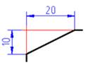
Length 2 |
The second length of the chamfer. |
||
|
Angle |
Angle of the chamfer. |
||
|
|
This button temporarily closes the dialog box to permit measuring the chamfer length and angle on the drawing. The Value picker dialog box appears to perform measurements. |
||
|
|
This button switches on the mode for cutting of full contour lines.
|
||
|
|
This button switches on the mode for cutting of partial contour lines before their intersection.
|
||
|
|
This button switches on the mode without lines cutting.
|
||
|
|
|
||
|
|
This button temporarily closes the dialog box to permit copying of properties from created chamfer. The command does not work on chamfers created with the participation of a polyline, since when setting a chamfer, all the components are collected into one polyline. |
||
|
|
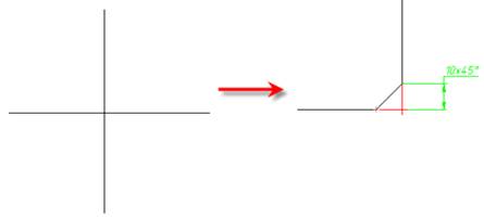
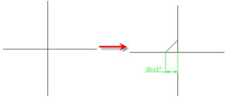
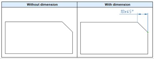
This button switches the automatic dimensioning mode on/off. In this mode, along with the creation of a chamfer, a dimensional object that measures it is automatically created.
|
||
|
|
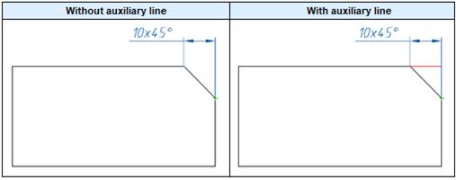
Build auxiliary lines – the switch that controls the display of an auxiliary line when dimensioning the chamfer.
|
||
|
Show at start |
When this check box is clear, Chamfer dialog box is not displayed, i.e. it allows you to reconfigure the command to work in a non-dialog mode. For a repeated call of the dialog, select the prOperties option in the command line or in the context menu. Such mode of operation is convenient, when you have to frequently use the command without changing its parameters. |
||
|
|
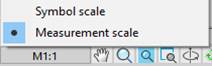
This drop list sets Object scale for dimension object.
|


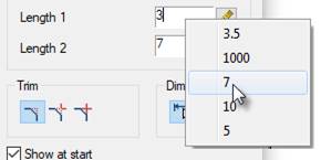
Double clicking or right clicking in the fields to enter values will open the context menu with a list of the recently entered values:
Options in the context menu and in the command line are available during the process of chamfer creation:
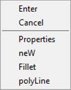
Command options:
|
Properties |
The Chamfer dialog box opens to change the chamfer parameters. |
|
neW |
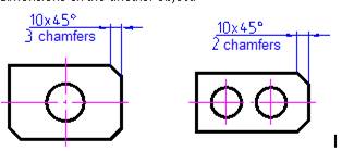
Finishes the creation of one group of chamfers and starts another. The command is applied when you need to create some chamfers with similar dimensions on one object and with the same dimensions on another object:
|
|
Fillet |
Switches to the mode for creating fillets. The Fillet dialog box opens to specify the parameters for the fillet. |
|
polyLine |
Switches to the mode of making chamfers along a whole selected polyline. Only segments with lengths which are more than chamfer length are processed. It is recommended to specify the same values for both chamfer lengths. This option is available for symmetrical chamfer. Auto dimensions and cutting of contour modes are ignored.
|
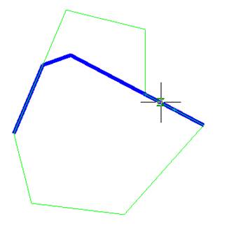
To create a chamfer:
1. Select the first object.
2. Hover over the second object. The chamfer options will be presented.
3. If there are no chamfer options, the message “Unable to create chamfer” will appear, select the Properties option from the context menu or command line and set the radius.
4. Select the second object.
5. Select a fillet from the options presented.
Features of the command operation
The command works in 3D. to perform the command, the original primitives should lie in the same plane.
If you press and hold the SHIFT key while selecting the second object, then a corner will be formed (snapping at the intersection point and cutting off).
When making an insertion of chamfers between adjacent sections of a polyline, a polyline retains its integrity.
If using the command, a chamfer is created between two polylines, then as a result it will be a single polyline object.
If you select segments of one polyline separated by other segments, then all these intermediate segments are deleted.
Chamfer Command, Non-dialog Option
Command line: CHA, CHAMFER
Building chamfers using the command line.
Specify first line or [?/Undo/POlyline/Distance/ANgle/Trim/mEthod/Multiple]:
Command options:
|
? |
Opens additional options for selecting objects. |
|
Undo |
Undoes the previous action in the command. |
|
POlyline |
Creates chamfers for all polyline vertices that are intersection points of two straight line segments. When the Trim > Trim mode option is set, the chamfer lines become new polyline segments. |
|
Distance |
Specifies the chamfer length from the intersection point of the first and the second objects. If both values are zero, then the selected objects or line segments are lengthened or trimmed to the intersection point. You can specify the length in the drawing or by entering a value in the command line. |
|
ANgle |
Specifies a chamfer along the length to the intersection point of the selected objects and the angle in the XY plane to the first object. |
|
Trim |
Controls the trimming of objects to chamfer lines. Trim – selected objects are removed to the end points of the chamfer lines. If objects do not intersect the chamfer line, they are extended or trimmed before the chamfer line is added. No trim – selected objects are not tirmmed. |
|
mEthod |
Selects the chamfer construction method. Distance – specifies two chamfer lengths. Angle – specifies the length and angle. |
|
Multiple |
Adds a chamfer to multiple sets of objects. |
Command prompt:
|
Specify first line or [?/Undo/Polyline/Distance/Angle/ Trim/mEthod/Multiple]: |
Select the object or the desired option to set the parameters. |
|
Specify second line or press Shift to select or [?/Distance/Angle/mEthod]: |
Select the second object or use the Shift key to form an angle in the crosspoint. To change parameters, select the required option. |