
 De
De  Es
Es  Fr
Fr  Pt
Pt 

-
-
-
-
-
-
-
-
-
-
-
-
-
-
-
-
-
-
-
-
-
-
-
-
-
-
-
-
-
-
-
-
-
Chain Note
-
-
-
-
-
-
-
-
-
-
-
-
-
-
-
-
-
-
-
-
-
-
-
-
-
-
Chain Note
 Ribbon: Home, Annotate – Leaders >
  Chain note
Menu: Draw – Notes >  Chain notes…
Toolbar: Utilities, Notes –
 Command line: NOTEH
The command opens the Chain note dialog box to set the note options:
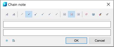
A chain note has several coaxial (collinear) leader points connected successively.
If the first leader node is placed on a straight line segment, the note will be located perpendicular to this segment.
Options:
|
|
Managing multiline text output above the leader. The transition to another line is performed by the CTRL+ENTER key combination. |
|
|
Framing the text under the leader. |


Use the icons to select the style of the extension line:
|
|
|
None. |
|
|
|
Arrow. |
|
|
|
Point. |
|
|
|
Open arrow. |
|
|
|
Half-arrow. |
|
|
|
Oblique. |


Use the icons to select the text alignment method:
|
|
|
By left edge. |
|
|
|
By center. |
|
|
|
By right edge. |


Other icons:
|
|
The Insert special symbol icon opens the panel with the table of special symbols, to select and insert them at the current cursor position in the text input field. |
|
|
The Notepad icon opens the Notepad dialog box. |
|
|
The Match properties icon temporarily closes the dialog box to specify the inserted leader whose properties should be copied and applied to the newly-created leader. |
|
|
The Add extension line icon is used to insert additional extension lines. The icon is available when you edit a chain note inserted into the drawing. |
|
|
The Global options button opens the Settings nanoCAD dialog box – Symbols tab |


By default, a chain note contains two input lines. The first line is for the caption above the leader landing, the second line is for the caption below the landing.
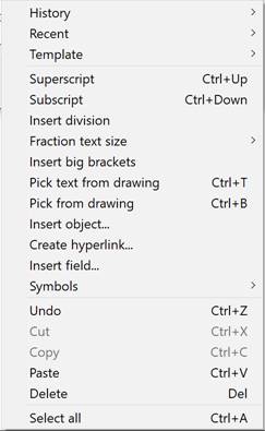
Right-click in the text field and choose the required menu item:
When you open the context menu on a leader arrow (without selecting the leader), a dialog box for selecting the arrow type will appear:
To create a chain note:
The Show dialog before inserting the object option is enabled
1. Run the command.
1. Run the command.
2. In the Chain note dialog box, select the required note options.
3. Enter the required text into the text fields.
4. Click OK.
5. Specify the first leader node. To select an object, take the sElection command in the command line or the context menu. To freely specify a point on the drawing, select the frEe command.
6. Specify the next leader nodes.
7. After specifying the last node, press ENTER.
8. Place a leader landing on the drawing.
The Show dialog before inserting the object option is disabled
1. Run the command.
2. Specify the first leader node. To select the object in the command line or the context menu, select the sElection command. To freely specify a point on the drawing, select the frEe command.
3. Specify the next leader nodes.
4. After specifying the last node press ENTER.
5. Place a leader landing on the drawing.
6. In the Chain note dialog box, select the required note options.
7. Enter the required text into the text fields.
8. Click OK.