
 De
De  Es
Es  Fr
Fr  Pt
Pt 

-
-
-
-
-
-
-
-
-
-
-
-
-
-
-
-
-
-
-
-
-
-
-
-
-
-
-
-
-
-
-
-
-
-
-
-
-
-
-
-
-
-
-
-
-
-
-
-
-
-
Calculate section characteristics
-
-
-
-
-
-
-
-
-
-
-
-
-
-
-
Calculate section characteristics
 Main menu: Mechanical - Design - Calculations >
 Calculate section characteristics.
Toolbar: Calculate section characteristics (toolbar "Calculations").
 Command line: MCGCS.
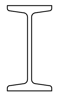
This command is used to calculate the geometric characteristics of the complex cross-sections with respect to arbitrary axes.
Calculation procedure
-
Call command.
-
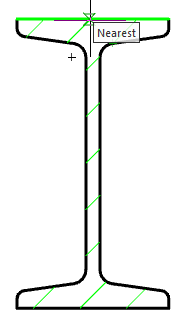
In the drawing, then click the area closed by one of the ways:
-
Clicking inside a closed area. Automatically determined by the outer loop of the closed area, and the area is added to the set.
-
Clicking on a closed polyline or circle. Adds the area bounded by polyline or circle.
Note: Repeated selection of the field deletes it from the set to calculate the cross-section. -
-
Complete the selection by clicking the right mouse button or the Enter key.
-
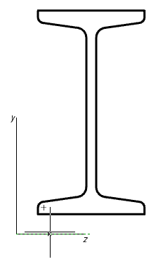
Specify the origin point or [central axis]. If you select the "central axis", the point of origin is automatically set in the center of mass of the cross section with an angle of rotation equal to 0 (step 5 is skipped).
-
Specify the angle of rotation of the coordinate system.
-
In the dialog box "Geometric section properties" Adjust the characteristics included in the summary table of the results.
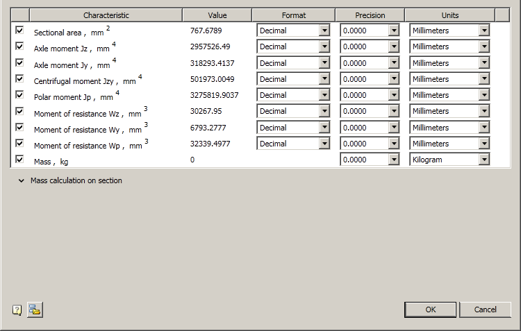
For each characteristic, you can customize your format (except weight), and the accuracy of the unit.
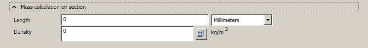
To calculate the weight you need to open an additional menu "Mass calculation on section", which indicate the product density and length. When you specify the length of the need to expose the units. When you specify the density, you can use the base materials, by clicking on the button
 "Material selection".
Customized settings display characteristics (size, precision, units) stored for later calculations sectional characteristics. To return to the default settings, press the button
 "Load default settings".
 -
Click "OK" in the dialog box and enter the drawing an insertion point of the table with the calculated parameters.
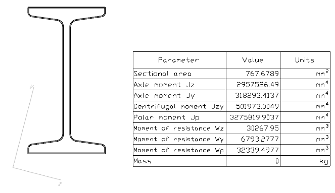
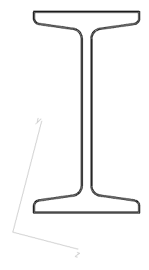
After the calculation is added to the drawing object nanoCAD Mechanica, comprising a cross-section schematic outline and the main central axis. The lengths of the axes are proportional to the values of the corresponding axial moments of inertia.