
 De
De  Es
Es  Fr
Fr  Pt
Pt 

-
-
-
-
-
-
-
-
-
-
-
-
-
-
-
-
-
-
-
-
-
-
-
-
-
-
-
-
-
-
-
-
-
-
-
-
-
-
-
-
-
-
-
-
-
-
-
-
-
-
-
-
-
-
-
-
-
-
-
-
-
-
-
-
-
-
-
-
-
-
Bound forms
-
-
-
-
-
-
-
-
-
-
Bound forms
Bounding hatch
 Main menu: Construction - Bound forms -
  Bounding hatch.
Ribbon: Construction - Symbols - Bounding hatch.
Toolbar: Bounding hatch ( "Bound forms").
 Command line: SPBHATCH.
Ground border
Main menu: Construction - Bound forms -  Ground border.
Ribbon: Construction - Symbols - Ground border.
Toolbar: Ground border ( "Bound forms").
Command line: SPGBORDER.
Heat isolation
Main menu: Construction - Bound forms -  Heat isolation.
Ribbon: Construction - Symbols - Heat isolation.
Toolbar: Heat isolation ( "Bound forms").
Command line: SPHISOL.
Water isolation
Main menu: Construction - Bound forms -  Water isolation.
Ribbon: Construction - Symbols - Water isolation.
Toolbar: Water isolation ( "Bound forms").
Command line: SPWISOL.
Bar strip
Main menu: Construction - Bound forms -  Bar strip.
Ribbon: Construction - Symbols - Bar strip.
Toolbar: Bar strip ( "Bound forms").
Command line: SPDBAND.
The special lines include: bounding hatch barstrip, heat isolation, water isolation, ground border. Lines have a wide range of applications. For example, the line-border soil formation on geological section.
Drawing bound forms
-
To draw a bound form, select the desired Dialog box bounding hatch.
-
You can immediately apply contour shading on the polyline using the command Simple Polyline context menu.
-
To build a complex contour on the basis of the drawing objects you can use the command M-magnet context menu.
-
If you want to create a new path, select the first point and then successively adding segments of the contour line, as is done when creating polylines. In the context menu commands are available for selecting the next segment (line segment or arc) and the method of construction.
-
To complete the construction of the circuit, press Enter.
-
In the next window boundary forms can change the type of boundary hatch. Button
 Hatch side is used to change the part of the overlay relative to the boundary contour shading:
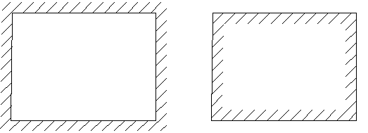
To change the contour and side hatch overlay grips (Grips) can be used.
When drawing certain types of boundary forms (notation waterproofing, insulation and dashed lines) before building the circuit the values of hatching must be specified. The values given are based on the current scale nanoCAD Construction 25.
Editing the values of the parameters can be made through the Properties panel (Properties) nanoCAD. For example, the entered value corresponds to 4 400 mm on the standard scale M100.