-
-
-
-
-
-
-
-
-
-
-
-
-
-
-
-
-
-
-
-
-
-
-
Block Insertion
-
-
-
-
-
-
-
-
-
-
-
-
-
-
-
-
-
-
-
-
-
-
-
-
-
-
-
-
-
-
Block Insertion
 Ribbon: Home, Insert – Block >
  Insert
 Menu: Insert –
  Block…
 Panel: Draw –
 Command line: I, INSBL, INSERT
A block insertion is also possible using the File Explorer functional bar.
The command inserts blocks or drawings (with *.dwg or *.dxf extension) in the current document.
If the rotation angle is specified, the point of its insertion is selected as the center of rotation. If the block’s rotation angle is specified on the screen (by defining the point), the oblique angle of an imaginary line drawn from the specified point to the block insertion point is taken as the rotation angle.
After insertion in the drawing, the block is processed as a single object. To ensure the possibility to work with individual objects that form the block, it can be exploded during insertion by selecting the Explode checkbox in the Insert block dialog box, or after insertion by using the Explode command from the Edit menu.
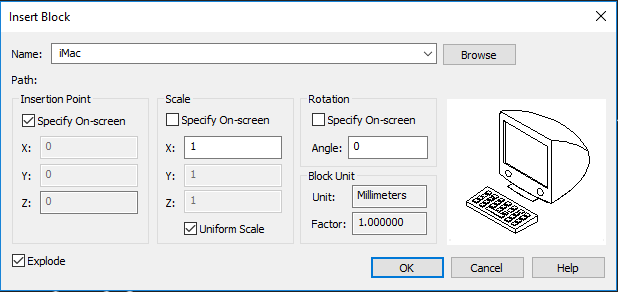
To specify the parameters of the block being inserted the command opens the dialog box:

Options:
|
Name: |
Drop-down list to select the name of the block being inserted. An empty list means that this document does not contain any block. |
|
Path: |
Displays information about the path along which the block is located. |
|
|
Button to open a standard files selection dialog box, were it is possible to select a block or a file to insert in the document. Data of the file being inserted are copied into the table of blocks of the current document as the block definition. |
Insertion point
|
Specify On Screen |
Turns on/off the mode for selecting the block insertion point by cursor on the screen after the dialog is closed. |
|
X: Y: Z: |
Fields to specify coordinates of block insertion point. |
Scale
|
Specify On Screen |
Turns on/off the mode for specifying the scale by cursor on the screen after the dialog is closed. |
|
X: Y: Z: |
Fields to enter scale factors by X, Y, Z axes. |
|
Uniform scale |
Turns on/off the mode of automatic application of the scale specified for X axis to Y and Z axes. |
note If, when inserting a block, you specify a negative scale value along any axis, the block will be mirrored relative to this axis.
note For inserting blocks containing 3D the use of a non-unit scale is blocked. If you specify different values for X: Y: Z:, when inserting a block with 3D, the value 1 will be applied for all dimensions.
Rotation angle
|
Specify On Screen |
Turns on/off the mode for specifying the block’s rotation angle by cursor on the screen after the dialog is closed. |
|
Angle: |
Enters the rotation angle for the block being inserted. |
Block units
|
Unit: |
Displays information on measurement units specified during the block creation. |
|
Factor: |
Displays the scale factor calculated as the ratio of the block’s measurement units to the drawing measurement units. |
|
Explode |
Turns on/off the mode for exploding the block into component objects during insertion. |


 De
De  Es
Es  Fr
Fr  Pt
Pt 

