
 De
De  Es
Es  Fr
Fr  Pt
Pt 

-
-
-
-
-
-
-
-
-
-
-
-
-
-
-
-
-
-
-
-
-
-
-
-
-
-
-
-
-
-
-
-
-
-
-
-
-
-
-
-
-
-
-
-
-
-
-
-
-
-
-
Balloons
-
-
-
-
-
-
-
-
-
-
-
-
-
-
Balloons
 Main menu: Mechanical - Part list >
 Balloons.
Ribbon: Mechanical - Part list >Balloons.
Toolbar: Part list >Balloons.
 Command line: MCPOSITION.
Fundamental rules
When you point to elements of attachment parts for nanoCAD Mechanica recognizes the size of parts mounting connections without additional indication of its components.
When making a specification of the assembly drawing mechanism can be set dynamically related to the title block of assembly component external DWG-file.
All changes in the linked drawing die subassembly (rooms, mass node) will automatically be reflected in the general specification.
Notation of the position of the standard item
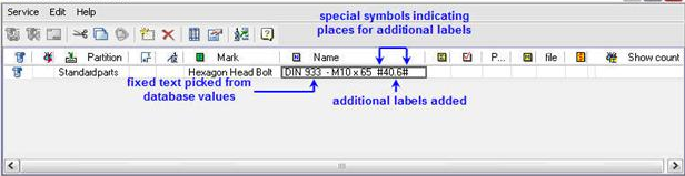
When selecting compounds for a fastening nanoCAD Mechanica Auto detects the typical preset sizes of fastening elements with no additional input. The construction indicators-fit , degree of hardness and the cover for standard parts should be set individually, depending on the specific conditions of the assembly operation.
Additional lables (Precision , modelling procedure, thread tolerance , degree of hardness etc , must be entered among the truss symbols. In the ballon editor (or in the part list editor), double click the entry field to enter additional information on the modelling procedure of a fastening.
The information input on performance of standard details.
Creating a Balloon
Pick the start point and the second point , defining the position of the underscore , the position leader edit dialog appears.
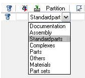
To group balloons according to the type, left click on the partition field.From the drop-down menu choose the desired option to which the part is referring.
The mark, Name, note and mass fields can be set by the user.
If the item name is too long, you can enable the forced transfer it to the next line. To do this, add a control character \n.

At the specification export, the posiotion name will be broken onto two lines.If the format is on the drawing then for the specification table the drawing zone is added automatically.
If a format is present on the drawing for positions on the specifications, the zone of the drawing is automatically added.
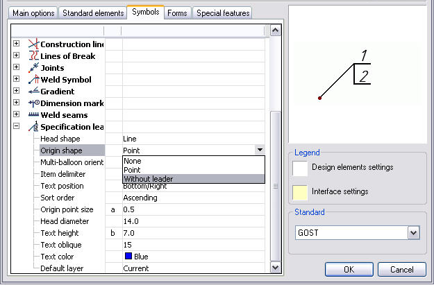
The shape of the balloon can be set in the symbol tabof the construction site 4 option below.
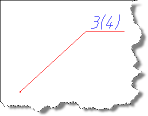
To display the quantity of positions connected with given leader, it is necessary to select the mark.
The total of the details of the given position will be displayed on the drawing next to the position number within brackets.
Going into the editor specifications

Checkboxes for the number of items, click on the icon Specification. This icon is located in the dialog editor specifications and in the main toolbar nanoCAD Mechanica.
Blocked Ballon Insertion on the drawing
If the ballon leader is applied to the item that has already been entered in the part list , it is shown in the figure with a vertical extension line.
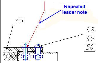
Repeated leader
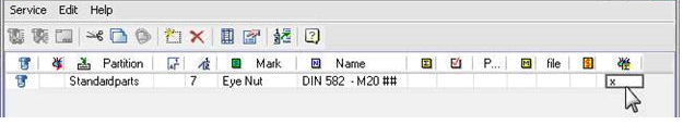
If such repeated ballons are meant to be any reason , double click the red leader.
In the dialog window, double-click on each of x-symbols in the column used to block ballon insertions.
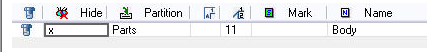
Close the window by clicking x symbol in the upper right corner the part numbers will appear in the drawing.
Adding Construction Indicators to Standard Parts
When you point to elements of attachment parts for nanoCAD Mechanica recognizes the size of parts mounting connections without additional indication of its components. Design features (landing, strength class, coating) standard parts, depending on the specific conditions of the site must be specified separately.
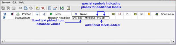
Additional notation (class, performance, tolerance thread, class, etc.) must be entered instead of a hash sign ("#").
Editor position (or BOM editor), double-click on an editable cell to enter additional information about the execution of the fastener.
When selecting components for a fastening, nanoCAD Mechanica auto-detects the typical preset sizes of fastening elements with no additional input. The construction indicators - fit, degree of hardness and the cover for standard parts should be set individually, depending on the specific conditions of the assembly operations.
Additional labels (precision, modelling procedure, thread tolerance, degree of hardness etc.) must be entered among the truss symbols. In the ballon editor (or in the part list editor), double-click the entry field to enter additional information on the modelling procedure of a fastening.
The information input on performance of standard details