
 De
De  Es
Es  Fr
Fr  Pt
Pt 

-
-
-
-
-
-
-
-
-
-
-
-
-
-
-
-
-
-
-
-
-
-
-
-
-
-
-
-
-
-
-
-
-
-
-
-
-
-
-
-
-
-
-
-
-
-
-
-
-
-
-
-
-
-
Automatic tracing
-
-
-
-
-
-
-
-
-
-
-
-
-
-
-
-
-
-
-
-
-
-
-
-
-
Automatic tracing
 Main menu: Construction - Communications >
 Automatic tracing.
Toolbar: Communications >Automatic tracing.
 Command line: SPTRACINGADD.
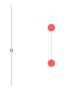
Team automatically separates trace on the already established relations between ports.
The guide trace
In order to build the correct trace, it is necessary to construct the auxiliary directional trace, which may for example, be positioned along the walls.
Auxiliary trace - trace which is set to "Directional trace" ("Yes").
Building trace
To build trace should:
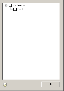
1. Select the command "Automatic tracing"
2. Specify equipment, ports and directional trace, or select all of the active network by pressing "Enter".
If there is no specified equipment and ports or derectional trace, a dialog appears offering to separate trace on the network.

5. After selecting objects in the dialog "Connection Type" select the types of connections through which trace should be diluted.
6. Confirm your selection. The trace is automatically built according to the design rules.
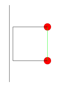
| Note: |
If the guide has the same pattern as the communications facilities, communications facilities will be connected to the rail. |
If necessary, you can cancel by trace, rail and adjust the command again or manually edit the trace built.