
 De
De  Es
Es  Fr
Fr  Pt
Pt 

-
-
-
-
-
-
-
-
-
-
-
-
-
-
-
-
-
-
-
-
-
-
-
-
-
-
-
-
-
-
-
-
-
-
-
-
-
-
-
-
-
-
-
-
-
-
-
-
-
-
-
-
-
-
-
Auto
-
-
-
-
-
-
-
-
-
-
-
-
-
-
-
-
Auto
 Main menu: Dimensions >
 Auto.
Auto.
Ribbon: Annotate - Dimensions >Auto.
Ribbon: Mechanical - Symbols >Dimensions.
Toolbar: Dimensions >Dimensions.
 Command line: MCMDIM, MDIM.
When inserting dimensions, context menu commands are available to switch the dimension view:
- Auto
- Aligned
- Horizontal
- Vertical
- Radius
- Diameter
- Large arc radius
- Arc
- Ordinate
- Angle
- Chain
- Base
- Properties (Opens the size edit dialog)
- Group
| Note: |
If you hold down the CTRL key while placing linear dimensions at the time you select the dimension line, you can skew the dimension extension lines. If you hold down the SHIFT key while placing linear or angular dimensions while selecting the position of the dimension line, you can move the dimension text along the dimension line. |
Linear dimensioning
To apply the dimension you need:
1. Select a segment;
2. Place the dimension number.
Dimensions can change to horizontal, vertical, or parallel, depending on the position of the drop point.
Dimensioning by selecting characteristic (anchor) points
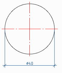
To apply dimensions, you must:
1. Select the first node;
2. Select the second node;
3. Place the dimension number.
When selecting anchor points of the circle, the diameter sign is automatically set.
Dimensioning between two parallel lines
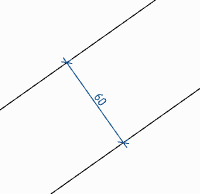
To apply the dimensions shown above, you must:
1. Select the first segment;
2. Select the second segment;
3. Place the dimension number.
Dimensioning through a point perpendicular to the selected line
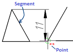
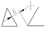
To apply the dimensions shown above, you must:
1. Specify the segment, perpendicular to which the dimension will be applied;
2. Without interrupting the commands, point to the end point of the line segment (a circle of small diameter should appear around the point);
3. Place the dimension number.
Undo an erroneously inserted dimension without exiting the command
Dimensioning is performed in a cyclic mode, i.e. when applying one dimension, the team does not stop its work, but suggests setting the next dimension or choosing a different type of dimension. In some cases, the previous dimension may not be set correctly. To remove an erroneous dimension, there is the "Undo" context menu command. You can also call the command with the "Ctrl + Z" hotkeys. The command is available when setting the dimension after specifying the dimension number.
Auxiliary markers
Auxiliary autodimension markers appear when you hover over a drawing object and show what type of dimension will be built in this case:
-
 Indicates that the diametral dimension will be drawn.
 -
 Shows what a linear dimension will be drawn (horizontal, vertical or parallel).
 -
 Shows that the angular dimension will be drawn.
 -
 Shows that the chain of dimensions will be built.
 -
 Shows that the slanted dimension will be drawn.
 -
 Indicates that the radial dimension will be drawn.