
 De
De  Es
Es  Fr
Fr  Pt
Pt 

-
-
-
-
-
-
-
-
-
-
-
-
-
-
-
-
-
-
-
-
-
-
-
-
-
-
-
-
-
-
-
-
-
-
-
-
-
-
-
-
-
-
-
-
-
-
-
-
-
-
-
-
-
-
-
-
-
-
Array of polar axes
-
-
-
-
-
-
-
-
-
-
-
-
-
-
-
-
-
-
-
-
-
-
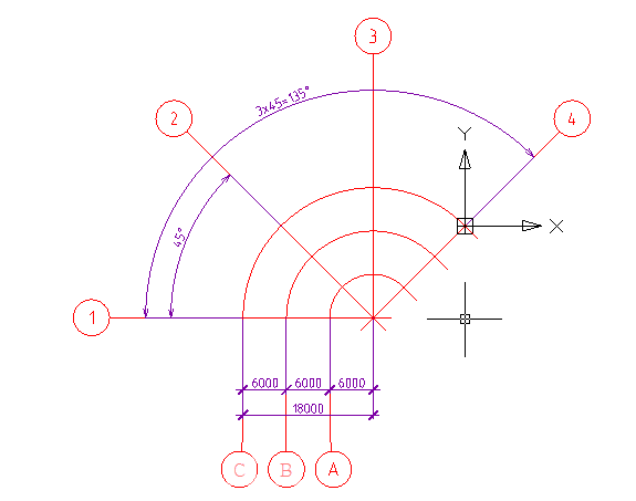
Array of polar axes
 Main menu: Construction - Coordinate axes -
  Polar grid.
Ribbon: Construction - Architecture - Polar grid.
Toolbar: Polar grid ( "Coordinate axes").
 Command line: SPPGRID.
Dialog array axes has two tabs - Digital and Letter to adjust accordingly alphanumeric array axes.
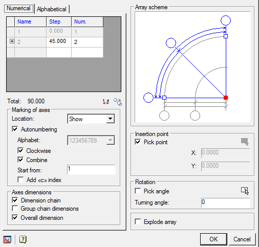
In the table, select the first line step between adjacent axes (degrees for digital and literal axes mm) and the total number of axes. You can create multiple sequences with different axes step between the axles and a different number of axes in each sequence. To do this, the bottom line in the Step column select the desired step value. The new line will be added automatically.
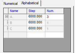
Meaning the first step in the alphabet first axis determines the distance from the center axis of the array.
Button  allows you to copy the settings from another array axes inserted into the drawing.
Button  reverses the number and letter codes.
Tool Group Labeling axes includes the following elements:
list of markers to select the position of the markers in the array axes or to disable their display.
Available options markers arc axes Start\End \On both sides\Castle\Hide.
Available options markers radial axes Show\Hide.
in the entry field Start with specified value of the first axis. By default, digital axes numbering starts at "1", for the letter - from "A".
Switch Add C index to the axis name.
switch Autonumbered to control automatic placement of axis numbers.
Available options Autonumber radial axes Clockwise\CCW \disabled .
Available options Autonumber arc axis from the center of\K Center\Disable.
Tool Group Axial dimensions contains two switches that serve to control the display size between the axes of the array:
- dimension chain
- group chain dimensions
- overall dimensions
In the graphics window, specify the position of the base point in the array, which will correspond to the insertion point. Move the cursor to the desired site and click the left mouse button. Base point indicated by the red squares.
By default, when you insert the array you want to specify the insertion point in the drawing. To disable this mode, clear Specify a point. In the fields below, specify the X, Y coordinates of the insertion point, or select a point on the drawing by clicking
 .
.
Switch Pick angle serves to activate the visual selection angle array axes. If required, enter the exact value of the angle of rotation in the input field, enter the angle in the drawing by clicking
.
Turn on the switch Explode array if you want to insert an array broken into separate axis and axial dimensions.
When the switch is on group size, the size of the axes will be as follows:
On the drawing you can edit individual array axis. Call of axis editing can be done by double-clicking on the marker axis (you must enable edit mode by double-clicking in the settings nanoCAD Construction 25).
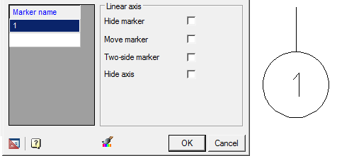
You can change the name of the marker (if configured array mode is in state of disabled Autonumbering).
Controls the display of the axis by means of a switch Hide axis .
Double click, you can change the value of the axial sizes (included in the chain, or the total size). When resizing shifted all axes, watching this.
The drawing can be edited using an array of axes grips.