

 De
De  Es
Es  Fr
Fr  Pt
Pt 

Anchor
 Main menu: Construction - Utilities >
 Anchor.
Ribbon: Construction - Symbols >Anchor.
Toolbar: Utilities >Anchor.
 Command line: SPANCHOR.
The command is intended for drawing end markers on line segments.
Procedure
1. Call the command "Anchor". A dialogue will open "End markers of lines".
2. In the "End markers of lines" dialog select the type of end markers and set their parameters. Click the "OK" button.
3. Specify the necessary lines or polylines in the drawing. "End markers" objects are created from from. Press the "Esc" key to end the circular mode for specifying objects.

Dialog
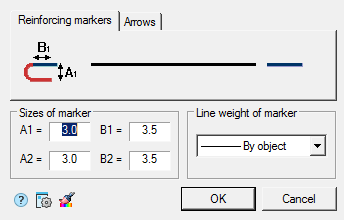
The "End markers of lines" editing dialog contains:
The panel of tabs for selecting marker types.
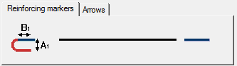
The "Reinforcing markers" tab allows you to define reinforcement markers.
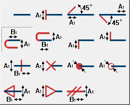
To change, select a marker for the first or second end of the segment by clicking on the graphics field (the button with the reinforcement marker image) and selecting one of the following options:
The "Arrows" tab allows you to define arrows.
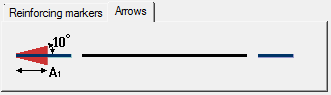
To change, select the arrow for the first or second end of the line segment by clicking on the graphic field (the button with the arrow) and choosing one of the following options:
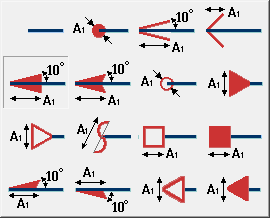
"Size of marker" group
Input fields "A1", "A2", "B1", "B2" - allow you to specify the corresponding sizes of markers in the current scale nanoCAD Construction 25. The fields used are indicated on the image of the markers.
Group "Line weight of marker"
Drop-down list "Line weight" - allows you to select the line weight of markers.
Additional commands
The  "Copy Properties" button - allows you to copy the appearance of end markers and their dimensions from a line with reinforcement or arrow markers in the drawing.