

 De
De  Es
Es  Fr
Fr  Pt
Pt 

Line Types Toolbar
 Ribbon: Home – Annotation >
  Line Types
Menu: Format – Line Types…
 Command line: STYLEEDITCMD, LINETYPE, LT
The Line Types toolbar is used to load, set, create and save line types in the current document, as well as to create custom linetype samples (templates). Using different line types to create different objects improves visual perception of graphic data and makes working with drawings more efficient.
Line type is a repeated sequence of lines, dots and spaces along a line or curve. Complex types of lines can contain built-in shapes which are stored in the (*.shx) shape file.
The MAXNUMPATTS system variable defines the maximum number of linetype samples in an object. Valid values range from 0 to 1,000,000. The default value is MAXNUMPATTS = 10,000. If the specified value is exceeded, the line is displayed on the screen as a solid line. Setting the variable to 0 removes the limitation, and lines are drawn according to the sample regardless of the number of samples. However, removing the limitation may result in reduced performance on busy drawings with long lines.
Line types are stored in files with a *.lin extension. Every type has its own name; sequence of dashes, points, relative lengths of dashes and spaces and other characteristics are specified in a line’s description. One lin-file can contain many line types.
nanoCAD supports line types created for AutoCAD.
Users can create their own line types by adding their descriptions to an existing LIN-file or creating their own new files. Edit an existing file or create a new file in any text editor or text processor. The Line Types toolbar is used to load, set, create and save line types in the current document.
User line types (*.lin) and shape files (*.shx), which are used in line types are stored in C:\ProgramData\Nanosoft AS\nanoCAD x64 26.0\SHX folder.
You can also use the Editor at the bottom of the toolbar to create custom line types and edit existing ones.
Before using a line type, you have to load it into the drawing.
Line types are saved with the document in a *.dwg file. They can also be saved for transfer to another computer in a template file (*.dwt).
|
|
Note |
|
The Line Type drop-down list in the Properties dialog box contains only the line types loaded in the document and displayed in the Line Types dialog box. |

Loaded line types can be renamed when you are working with the drawing. Renaming a line type only changes its description in the current drawing; the name of the line type stays the same in the LIN-file.
|
|
Note |
|
By layer, By block and Solid line types cannot be renamed or deleted. |
Line types can be assigned not only to layers, but also to objects. To change an object’s line type, replace it on the layer with another line type, change the line type of the layer where it is placed or specify another line type especially for the object.
Linetypes that are not used in a drawing can be deleted either in the Linetypes toolbar or using the PURGE (-PURGE) command.
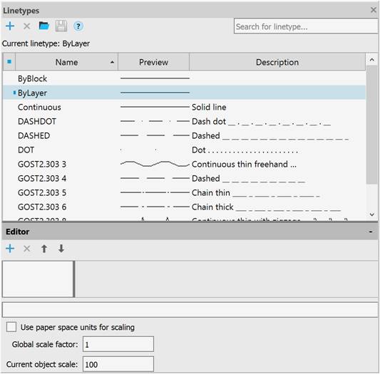
The top of the toolbar displays the name of the current linetype, the linetype search field, and buttons:
|
|
New |
Creates a new linetype based on the selected one. |
|
|
Delete |
Deletes the selected linetype from the current document. |
|
|
Load |
Imports linetypes into the current document. |
|
|
Save |
Saves the selected linetypes to a file with the *.lin extension. |
The list of linetypes loaded in the current document is presented as a table with columns:
|
|
Displays and sets the current linetype. The current linetype is marked with the All newly created objects inherit the linetype set by the current one. When the current line type is set to By Layer, new objects will be created with the linetype assigned to the current layer. |
|
Name |
Displays and edits the name of the selected linetype. |
|
Preview |
Visual display of the linetype. |
|
Description |
Displays and edits brief information about the linetype. |

 sign.
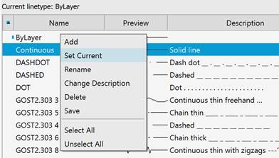
sign.To perform operations with linetypes, commands are available in the context menu:
|
Add |
Creates a new linetype based on the selected one. |
|
Set Current |
Sets the selected linetype as current. |
|
Rename |
Edits the name of the selected linetype. |
|
Change Description |
Edits the text description of the selected linetype. |
|
Delete |
Deletes the selected linetypes from the current document. |
|
Save |
Saves the selected linetypes to a file with the *.lin extension. |
|
Select All |
Selects all linetypes in the list. |
|
Unselect All |
Deselects the linetypes selected in the list. |
Linetype editor opens when clicking the  sign.
sign.
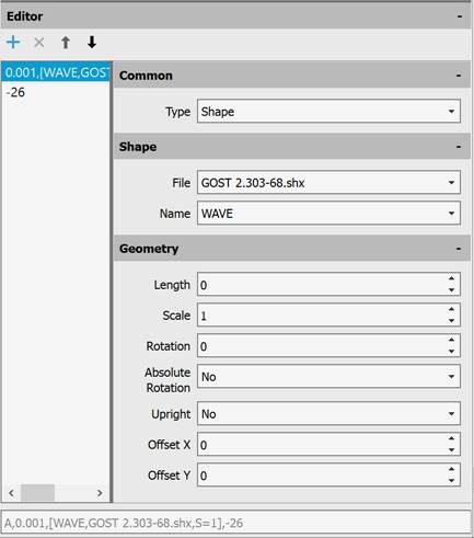
The following buttons are located immediately below the title:
|
|
Add row |
Adds a new line drawing element. |
|
|
Delete row |
Deletes a line drawing element. |
|
|
Move up |
Moves one line drawing element up. |
|
|
Move down |
Moves one line drawing element down. |
The left part of the editor displays the description of the linetype sample.
The following sections are displayed on the right: Common, Shape, Geometry.
The Common section displays the line drawing element type. The following options are available in the drop-down list: Dash, Text, Shape.
In the next section, for the Text element type, select the style and enter the text; for the Shape element type, specify the file and shape name.
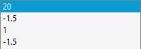
The Geometry section displays the value of the line drawing element.
In the last field of the editor, you can copy the linetype description for subsequent editing in a text editor.
The following parameters are configured at the bottom of the Linetypes toolbar:
|
Use paper space units for scaling |
Sets the same scale for linetypes in paper and model spaces. This option is useful when using several viewports at the same time. |
|
Global scale factor: |
Sets the global scale factor value for all linetypes. |
|
Current object scale: |
Sets the linetype scale value for newly created objects. The resulting scale is equal to the product of the global scale and the current scale. |
1. Select the line type on which the new one will be based.
2. Click the  New button (or select Add in the context menu).
A new row with the default name LineTypeN will appear in the list of linetypes, where N is the ordinal number of the created linetype, starting with 1.
3. To rename, click in the Name column (or select Rename in the context menu) and specify the name for the new linetype. The name should contain at least one character. Names should not be duplicated. Invalid characters for a layer name are: < > / \ “ ” : ; ? * | , = ` tab character.
4. Click in the Description column (or select Change Description in the context menu) and specify the description for the new linetype.
5. Make the necessary changes in the Editor.
1. Select the linetype for editing by left-clicking on it. The lower field displays the description of the selected linetype.
2. Select the line drawing element in the left part of the editor by clicking on it.
3. For the Dash element type, the Common (Type), Geometry (Length) sections are available in the right part of the editor.
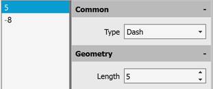
Enter a new value in the Length field.
|
|
Note |
|
When a positive value is specified, a dash is constructed; when a negative value is specified, a space is constructed; when the length is zero, a dot is constructed. |
|
|
Note |
|
The length of the first line drawing element should be greater than or equal to zero, i.e., a dash or dot should be constructed first. |
4. For the Text element type, the following sections are available in the right part of the editor: Common (Type), Text (Style, Text), Geometry (Length, Scale, Rotation, Absolute Rotation, Upright, Offset X, Offset Y).
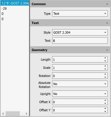
In the Style field, select the text style from the drop-down list, and enter the characters in the Text field. In the Geometry section, set the required parameters.
5. For the Shape element type, the following sections are available in the right part of the editor: Common (Type), Shape (File, Name), Geometry (Length, Scale, Rotation, Absolute Rotation, Upright, Offset X, Offset Y).
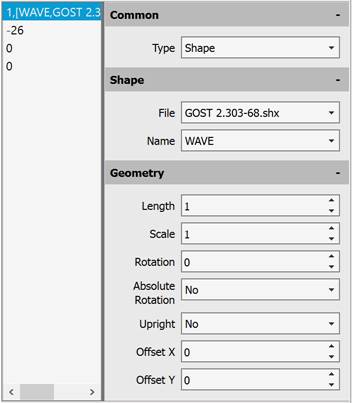
In the File field, select the file with the shapes from the drop-down list, in the Name field, select the shape name from the drop-down list. In the Geometry section, set the required parameters.
6. To add a new line drawing element, click the Add row button. The new line drawing element is added at the end of the list, by default it is assigned the Dash type, length 0 (dot).
7. To delete a line drawing element, click the  Delete row button.
8. To change the sequence of line elements, use the  Move Up,
  Move Down buttons.
1. Select one or more linetypes in the dialog to delete. To select several linetypes, press and hold the SHIFT key; to add any element from the list to the selection, select with the CTRL key pressed.
2. Click the Delete button.
|
|
Note |
|
The following linetypes cannot be deleted: |
1. Click the  Load.
Load.
2. In the Open Line Type Import dialog box, specify the path to load the line type file (*.LIN), containing the descriptions of the line types.
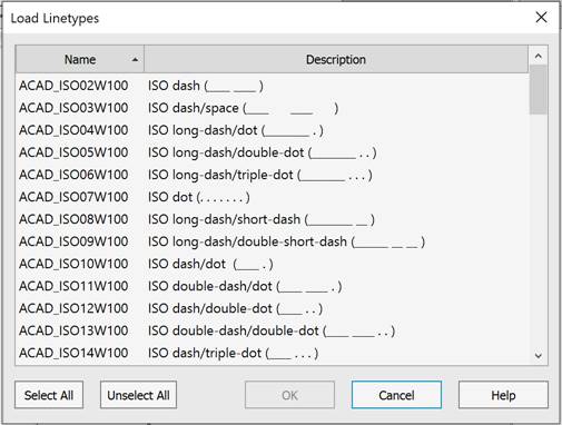
3. In the Load Linetypes dialog box, select the line types for import. To select several line types, use the SHIFT or CTRL buttons. To select all linetypes at once, click Select All. To cancel the selection, click the Unselect All button.
When attempting to add a linetype with the name of a linetype that already exists in the drawing, a warning message appears:
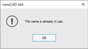
You can configure the message display options in the Show messages section of the OPTIONS dialog.
4. Click OK to start loading the selected line types. The selected linetypes will be displayed in the table of the Linetypes toolbar.
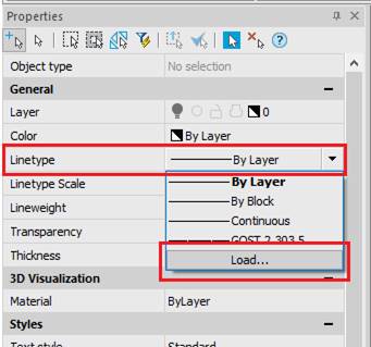
You can also load linetypes from the Properties bar by selecting the Load… item in the Linetype drop-down list:
1. Select one or more line types for export in the list (you can use the SHIFT and CTRL keys when selecting).
2. Click the  Save button.
3. In the Save linetype file dialog that opens, specify the folder and give it a name.
4. Click the Save button.
Creating and Editing Linetypes in the Text Editor
You can view and, if necessary, edit the content of GOST 2.303-68.lin file in any text editor that saves data in ASCII format:
;;
;; linetypes by GOST 2.303-68
;;
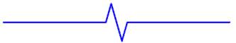
*GOST2.303 3,Solid wavy ~~~~~~~~~~~~~~~~~~~
A,0.001,[WAVE,GOST 2.303-68.shx],-26
*GOST2.303 4,Dashed __ __ __ __ __ __ __ __ __
A,5,-2,0
*GOST2.303 5,Dash-dot thin ____ _ ____ _ ____ _ ____ _
A,20,-1.5,1,-1.5
*GOST2.303 6,Dash-dot theckened ___ _ ___ _ ___ _ ___ _ ___ _ ___
A,8,-1.5,1,-1.5
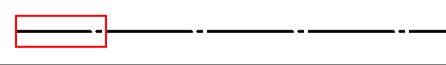
*GOST2.303 8,Solid thin kinks ---'\---'\---'\---'\---'\---
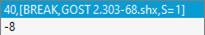
A,40,[BREAK,GOST 2.303-68.shx],-8
*GOST2.303 9,Dash-dot with two dots __..__..__..__..__..__..__..__.._
A,20,-1.5,1,-1.5,1,-1.5
Lines that start with a semicolon (;) character are comments.
Description of a linetype consists of 2 lines: the first line contains the linetype name and a short description, the second line specifies the linetype outline.
*GOST2.303 5,Dash-dot thin ____ _ ____ _ ____ _ ____ _
A,20,-1.5,1,-1.5
An asterisk is placed before the linetype name. The name should be unique.
*GOST2.303 5
The linetype name is separated from a short description by a comma.
*GOST2.303 5,Dash-dot thin ____ _ ____ _ ____ _ ____ _
A brief description consists of a text part explaining the purpose of the linetype (for example, the explanation Dash-dot can be changed to the following: To draw center lines). The description often includes a sequence of text characters (dashes, spaces, dots, etc.) that visually resembles this line. The description can be up to 47 characters long. The description is optional and can be omitted. If there is no description, no comma is placed after the linetype name.
The second line containing the linetype description begins with the character A, which defines the type of alignment.
Further, separated by commas (without spaces), write the linetype elements that specify the line style.
A,20,-1.5,1,-1.5
As elements of the linetype outline, the following can be used:
· zero – specifies a dot construction;
· positive decimal numbers – specify the construction of dashes (a number value determines the dash length in drawing units);
· negative decimal numbers – specify the construction of spaces (a number value determines the space length in drawing units);
· text objects;
· embedded shapes stored in form files.
Linetypes described by dashes, dots and spaces are called simple. The complex linetypes include the ones described by text objects and embedded shapes. Linetypes that include text objects and embedded shapes are used in utility network signs, in topographic symbols, and so on.
In the GOST 2.303-68.lin file the linestypes *GOST2.303 4, *GOST2.303 5, *GOST2.303 6 and *GOST2.303 9 are simple, the linetypes *GOST2.303 3 and *GOST2.303 8 are complex, because their descriptions use the embedded shapes WAVE and BREAK.
Alignment type A determines the condition according to which lines should begin and end with dashes, i.e. the value that determines the length of the first segment of the line should be greater than or equal to zero.
In order to better understand what alignment is and how it works, consider an example of drawing a line segment from point 1 to point 2 using Dash-Dot linetype. The program will construct a segment in such a way that it starts at point 1 and ends at point 2 with dashes. If necessary, the first and last dashes can be lengthened to meet the alignment condition. For a short segment, if it does not contain even one link long_dash-space-short_dash-space, the program will draw one dash (continuous line).
The linetype description line should not exceed 80 characters.
For each linetype it is possible to define no more than 12 elements.
In the linetype description, it is enough to specify one repeating fragment (link). For example, for the Dash-dot linetype such fragment is the link long_dash-space-short_dash-space.
The format for determining a simple linetype is:
A,Length1,Length2,Length2,…
Text objects are generally described in a complex linetype definition in the following format:
[”Text”,Style,Scale,Rotation_angle,Offset_X,Offset_Y]
The format for writing the embedded shape in the definition of a complex linetype:
[Name,File]
or
[Name,File,Scale,Rotation_angle,Absolute_rotation,Offset_X,Offset_Y]
Parameters:
|
Option |
Brief information about the option |
Value examples |
|
Length |
The length of dash or space in drawing units. |
Values can be positive or negative numbers: 20, -1.5, 0.001 Value 0 – constructing a point. |
|
Text |
Text symbols used in a complex line. The option is used to describe a text object. |
Any set of text symbols: C, D, UK, W1, K1. |
|
Style |
The name of a text style. The option is used to describe a text object. |
The default style is Standard A style is available for selection in the drop-down list GOST 2.304 |
|
Name |
Shape name. The option is used to describe an embedded shape. Mandatory parameter – if it is absent, the linetype is not defined. If there is no from in the specified file (File option), the line is constructed without a shape. |
WAVE, BREAK, LINE FEED |
|
File |
The name of compiled (*.shx) rile containing a shape definition. The option is used to describe an embedded shape. Mandatory parameter – if it is absent, the linetype is not defined. Is there is no form file, a line is drawn without a shape. |
GOST 2.303-68.shx |
|
Scale |
The scale factor by which the height of the text style or the original height of the shape is multiplied. The format of the entry in the linetype description: S=value. If the height of the text style or the initial height of the shape are equal to 0, then the specified value of the S = parameter is used as the height. |
S=3, S=0.1, S=.1 |
|
Rotation angle |
The angle of rotation of a text object or embedded shape relative to the line direction. The format of the entry in the linetype description: R=value. It is allowed not to specify the parameter, in this case its value is assumed to be 0. |
R=0, R=30, R=-90 |
|
Absolute rotation angle |
The angle of rotation of a text object or embedded shape relative to the coordinate origin, i.e. all text objects or all shapes rotate the same regardless of their position relative to the line. The format of the entry in the linetype description: A=value. It is allowed not to specify the parameter, in this case its value is assumed to be 0. |
A=0, A=45, A=-30 |
|
Offset by X |
The offset of a text object or embedded shape by X axis directed along the line. The format of the entry in the linetype description: X=value. The parameter X=0 is set when describing a continuous line containing text objects or embedded shapes. It is allowed not to specify the parameter, in this case its value is assumed to be 0. The parameter S= does not affect the X offset. |
X=5, X=-2.5, X=0.01 |
|
Offset by Y |
The offset of a text object or embedded shape by Y axis perpendicular to the line. The format of the entry in the linetype description: Y=value. The parameter Y=0 is set when describing a complex line containing text objects or embedded shapes without offset by Y. It is allowed not to specify the parameter, in this case its value is assumed to be 0. The parameter S= does not affect the Y offset. |
Y=0.01, Y=-3.5, Y=7 |
Linetypes examples:
1. Definition of a simple linetype Dash-dot thin:
*GOST2.303 5,Dash-dot thin ____ _ ____ _ ____ _ ____ _
A,20,-1.5,1,-1.5
specifies the construction of a line that starts with a dash of 20 drawing units length followed by a space of 1.5 drawing units, then a dash of 1 drawing unit is built, then again a space of 1.5 units. This fragment (link) is repeated throughout the segment, ending at the end point with a dash of 20 drawing units:

2. Definition of a complex linetype Funny, containing text symbols 8 and ):
*Funny,Example of a custom linetype
A,10,-10,0.001,["8)",Standard,S=5,R=-90,X=-3,Y=3],-10

3. Definition of a complex linetype Arrow1 containing text symbols < and >:
*Arrow1,Single arrow
A,0.001,["<",Standard,S=5,Y=-2.5],25,[">",Standard,S=5,X=-2.5,Y=-2.5],-20

4. Definition of a complex linetype Arrow2 containing text symbols < and >:
*Arrow2,Double arrow
A,0.001,["<",Standard,S=5,Y=-2.5],0,["<",Standard,S=5,X=3,Y=-2.5],25,
[">",Standard,S=5,X=-2.5,Y=-2.5],0,[">",Standard,S=5,X=-5.5,Y=-2.5],-20

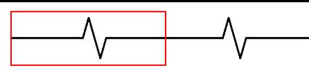
5. Definition of a complex linetype GOST2.303 8 containing the embedded shape BREACK:
*GOST2.303 8,Continuous jogged line ---'\---'\---'\---'\---'\---
A,40,[BREAK,GOST 2.303-68.shx],-8
6. Definition of a complex linetype A1 containing an embedded shape LEG_SIGN1:
*A1,Example of a custom linetype
A,10,-20,0,[LEG_SIGN1,CS_Gost2304.shx,S=5,R=180,X=-5.5,Y=2.5]

7. Definition of a complex linetype Dashed 14-4 containing embedded shapes ARROWFILL, CIRCLEFILL_IN and CIRCLEFILL_OUT:
*Dashed 14-4,Dashed line. under linear object <|---O---|>
A,0.01,0,[ARROWFILL,styles.shx,S=0.1,R=180,X=0.7],7,0,[CIRCLEFILL_IN,styles.shx,
S=0.1],0,[CIRCLEFILL_OUT,styles.shx,S=0.1],7,0,[ARROWFILL,styles.shx,S=0.1,X=-0.7],-4
