

 De
De  Es
Es  Fr
Fr  Pt
Pt 

-
-
-
-
-
Status Bar
-
-
-
-
-
-
-
-
-
-
-
-
-
-
-
-
-
-
-
-
-
-
-
-
-
-
-
-
-
-
-
-
-
-
-
-
-
-
-
-
Status Bar
 Ribbon: Manage – Customization –
  Status Bar
Menu: View – Status Bar
 Hotkeys: ALT+S
Command line: SHOWSTATUSBAR
There are interface elements in the status bar:
Current coordinates of the cursor:
|
Status bar element |
Description |
|
|
Display field for the current cursor coordinates. Cursor coordinates display modes: · dynamic display of cursor absolute coordinates in the Cartesian coordinate system when the cursor is moving, · display of relative distance in polar coordinates (distance<angle) when the cursor is moving. Switching to the relative distance mode is made automatically when specifying two or more points is required. |
|
|
Button to toggle snap mode (F9). |
|
|
Button to toggle grid mode (F7, CTRL+G). |
|
|
Button to toggle object snap mode (F3). |
|
|
Button to toggle 3D snap mode (F4). |
|
|
Button to toggle object tracking mode (F11). |
|
|
Button to toggle polar tracking mode (F10). |
|
|
Button to toggle ortho mode (F8). |
|
|
Button to toggle dynamic input mode (F12). |
|
|
Button to toggle the mode for building rectangular isometric projections. |
|
|
Button to toggle line width showing. |
|
|
Button to toggle the hatches showing. |
|
|
Multi-function button to switch between model space and paper space: · when working in model space, switches to the space of the last active layout. · when working in paper space, switches to model space of the viewport. |
|
|
Button to lock the scale of the selected viewport in paper space. Viewport lock is used to keep the previously set viewport scale unchanged (so that zooming inside the viewport does not affect the viewport scale). The button can be in four states: · · · · |
|
|
Sets the scale for the selected viewport in paper space. Not available when the viewport is locked |
|
|
Button to control the preview state of drawing objects in a selection set. |
|
|
Controls visibility of objects by isolating or hiding a selection set. |
|
|
Enables/disables selection for objects on locked layers. |
|
|
Button to display the Select Objects dialog. |
|
|
Button to display the floating Quick Properties mini bar. |
|
|
Dynamic UCS. |
|
|
Button to set symbol scale and measurement scale of an objects. |
|
|
Pan. |
|
|
Zoom. |
|
|
|
|
|
|
|
|
|
|
|
Button to start drawing regeneration. |
|
|
Button to lock/unlock interface elements to prevent accidental movement: · Docked toolbars; · Floating toolbars; · Docked windows; · Floating windows; · All locked; · All unlocked. For temporary unlocking – press and hold the Ctrl key. |
|
|
Button to indicate the presence of external reference in a drawing. When rolling over the button, a pop-up window appears on the absence or presence of external references. The button’s context menu contains the commands: External references – opening the function bar; Refresh external references. |
|
|
CAD standards: configuring standards, checking drawings for standards violations, notification of standards violation. |
|
|
Button to switch on/off full screen mode (CLEANSCREEN, FULLSCREEN command). |


 .
.


Managing Elements of the Status Bar
Use the Status Bar Configuration menu to set elements of the Status bar:
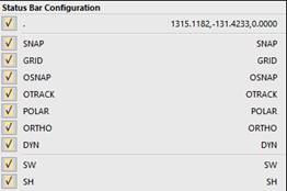
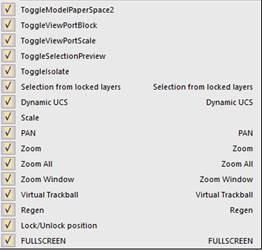
To open the context menu:
1. Right button click on the Status bar.
2. Select/deselect the required elements in the context menu.