

 De
De  Es
Es  Fr
Fr  Pt
Pt 

-
-
-
-
-
-
-
-
-
-
-
-
-
-
-
-
-
-
-
-
Multiline Styles Dialog Box
-
-
-
-
-
-
-
-
-
-
-
-
-
-
-
-
-
-
-
-
-
-
-
-
-
-
-
Multiline Styles Dialog Box
 Command line: MLSTYLECLASSIC
This command opens the classic version of the Multiline Styles dialog box, which is used for compatibility with previous versions of the program.
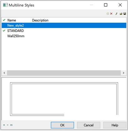
In the bottom part of the dialog there are preview area and buttons to zoom in and zoom out. Also, you can use mouse wheel to zoom:  Zoom in;
  Zoom out;
  Zoom 1:1.
Options:
|
|
List of available styles loaded to the document. |
|
|
Sets current style. |
|
Name |
Name of multiline style. |
|
Description |
Text description. |

Buttons
|
|
New |
Creates new multiline style based on selected. |
|
|
Delete |
Removes selected style from the current document. |
|
|
Edit |
Shows multiline style editor dialog. |
|
|
Load |
Loads multiline styles from file to the current document. |
|
|
Save |
Saves selected styles to *.mln file. |

To create multiline style:
1. Start Mline Styles command.
2. In Multiline Styles select desired style and click button  New. New style with default name MlineSyleN, where N – ordinal number starting from 1. will appear. All settings will be based on selected style.
3. Click button  Edit to start editing created style.
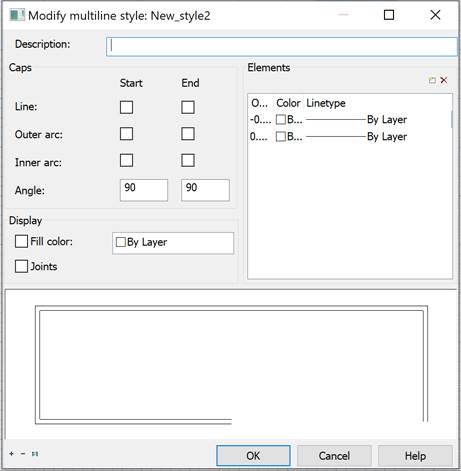
4. Set desired parameters and click OK.
Options:
|
Description |
Text description. |
|
|
Ends |
The type of end caps. |
|
|
Start End |
Sets the type of end caps for start and end of the multiline. |
|
|
Line |
Displays a line segment across each end of the multiline. |
|
|
Outer Arc |
Displays an arc between the outermost elements of the multiline. |
|
|
Inner Arc
|
Displays an arc between pairs of inner elements. If there's an odd number of elements, the center line is unconnected. For example, if there are six elements, inner arcs connect elements 2 and 5 and elements 3 and 4. If there are seven elements, inner arcs connect elements 2 and 6 and elements 3 and 5. Element 4 is left unconnected. |
|
|
Angle |
Specifies the angle of the end caps. |
|
|
Show |
Controls the background fill of the multiline |
|
|
|
Fill with Color |
Sets the background fill color of the multiline. When you choose Select Color, the Select Color dialog box is displayed. |
|
|
Joints |
Controls the display of the joints at the vertices of each multiline segment. |
|
Items |
Sets element properties, such as the offset, color, and linetype, of new and existing multiline elements. |
|
|
|
Offset |
Specifies offset from the middle of the multiline. Elements are displayed in descending order of their offsets. |
|
|
Color |
Specifies color. |
|
|
Linetype |
Specifies linetype for element. |
|
|
Add Item |
Adds new element. |
|
|
Delete Item |
Removes the selected element. |
Multiline Styles can be saved to *.mln file. You can save multiple multiline styles in one file.
1. In the Multiline Styles dialog click  Save button.
2. In Save Multiline Styles dialog select styles. Click OK.
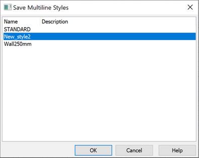
3. Specify the file name and path.
1. In the Multiline Styles dialog click  Load button.
2. Specify the file name and path.
3. In Load multiline style dialog select styles to load in the current document. Click OK.