De
De  Es
Es  Fr
Fr  Pt
Pt 

-
-
-
-
-
-
-
-
-
-
-
-
-
-
-
-
-
-
-
-
-
-
-
-
-
-
-
-
-
Linear Dimensions
-
-
-
-
-
-
-
-
-
-
-
-
-
-
-
-
-
-
-
-
-
-
-
-
-
-
Linear Dimensions
 Ribbon: Home, Annotate - Dimensions >
  Aligned
Menu: Dimensions  Aligned
Toolbar: Utilities –
Context menu when calling any dimension: Aligned
 Command line: MDIMALI
To apply a dimension, you need to:
1. Select the snap type in the command line:
nEarest snap gets object – dimensions the entire selected object;
nEarest snap gets point (by default) – sets the dimension nodes at the selected location on the object.
2. Specify the end nodes of the dimension depending on the selected snap type:
nEarest snap gets object – specify the object, the end nodes of the dimension will be the end points of the object;
nEarest snap gets point – specify the start and end nodes on the selected object.
3. Place the dimension number.
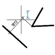
When setting a parallel dimension, an auxiliary marker appears .
.
Context menu when calling any dimension: Horizontal
 Command line: MDIMHOR
Context menu when calling any dimension: Vertical
 Command line: MDIMVER
Setting linear dimensions with the Linear command
Ribbon: Home, Annotate – Dimensions >  Linear
Menu: Dimensions –  Linear
Toolbar: Utilities, Dimensions –
Command line: DIMLINEAR
Setting linear dimensions with a horizontal, vertical or rotated dimension line.
1. Specify the starting points of the first and second leaders or press Enter to select an object.
2. Select the dimensioning option in the command line or context menu.
3. Specify the position of the dimension line.
Command options:
|
Mtext |
Enters multiline text. The Text Format bar opens. |
|
Text |
Enters or changes dimension text in the command line. |
|
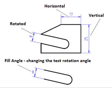
Horizontal |
Sets a horizontal dimension. |
|
Vertical |
Sets a vertical dimension. |
|
Rotated |
Sets the dimension at a certain angle. · Specify the rotation angle of the dimension line on the screen or in the command line. |
|
Fill Angle |
Changes the rotation angle of the dimension text. · Specify the rotation angle of the dimension text on the screen or in the command line. |
Setting linear dimensions by Auto command
Ribbon: Home, Annotation – Dimensions >  Auto
Auto
Menu: Dimensions –  Auto
Auto
Toolbar: Utilities, Dimensions –
Command line: MDIM
To dimension you can use also the Horizontal, Vertical and Aligned dimension commands.
Depending on the position of the placement point, the dimensions can change to horizontal, vertical or parallel.
Switching to “parallel” is performed when the cursor hits the middle part of a segment with a length of L/4 (where L is the segment length), i.e. L/8 to each side from the middle of the segment. For example, an almost horizontal segment with a length of ~100 mm (0.0) - (100.1) has a switching interval of 37.5 - 62.5:
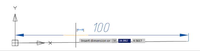
Interval 0-37.5
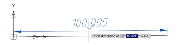
Interval 37.5-62.5
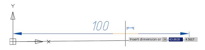
Interval 62.5-100
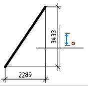
To specify the horizontal dimension of the line:
1. Place the cursor over the line to show its dynamic highlighting and display the auxiliary marker  . Left click to confirm the selection:
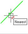
2. Move the cursor up or down until the auxiliary symbol  or
or  is displayed. Select the location of the dimension. Left-click to fix the selected position :
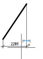
To specify the vertical dimension of the line:
1.
2.
3. Place the cursor over the line to show its dynamic highlighting and display the auxiliary marker . Left click to confirm the selection:
4. Move the cursor to the right or left until the auxiliary symbol  or
or  is displayed. Select the location of the dimension. Left-click to fix the selected position:
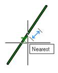
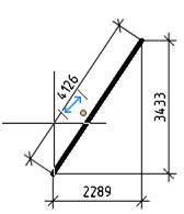
To specify the aligned dimension of the line:
1.
2.
3.
4.
5. Place the cursor over the line to show its dynamic highlighting and display the auxiliary marker . Left click to confirm the dimensioning:
Move the cursor to the right or to the left until the auxiliary symbol :
6. or  is displayed. Select the location of the dimension. Left-click to fix the selected position:
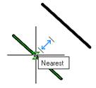
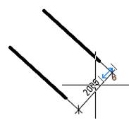
For dimensioning between two parallel line segments:
1. Place the mouse cursor over the first segment to highlight it dynamically and display an auxiliary marker . Left-click to confirm the selection:
2. Place the mouse cursor over the second segment to highlight it dynamically. Left-click to confirm the selection. This displays the linear dimension between the two parallel segments:
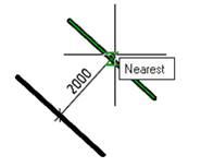
3. Move the cursor to the right or left until the auxiliary symbol or  is displayed. Select the location of the dimension. Left-click to fix the selected position:
To draw the dimension from a point to a line segment:
1. Place the mouse cursor over the segment to highlight it dynamically and display the auxiliary marker . Left-click to confirm the selection:
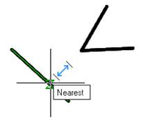
Place the mouse cursor:
2. over the point. Left-click to confirm the selection. This displays the linear dimension from the point to the segment:
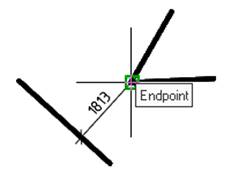
3. Select the location of the dimension. Left-click to fix the selected position: