
 De
De  Es
Es  Fr
Fr  Pt
Pt 

-
-
-
-
-
-
-
-
-
-
-
-
-
-
-
-
-
-
-
-
-
-
-
-
-
-
-
Insert External Reference
-
-
-
-
-
-
-
-
-
-
-
-
-
-
-
-
-
-
-
-
-
-
Insert External Reference
 Ribbon: Insert – Reference >
  DWG Reference
Menu: Insert –  DWG Reference
Toolbar: Draw –
 Command line: ATTACH, XA, XATTACH
External references allow you to add information from other drawings to the current document. It is possible to insert several external references into one document. Conversely, the same document can be used as an external reference in several other documents. External references can contain inserted external references. When you add an external reference, all external references inserted in it will also be displayed in the current drawing.
External references can only link external documents to the current document. The objects placed in the drawing file with external references are displayed in the current drawing with other objects in this drawing, but they are not added into the drawing. The external reference is a kind of label that indicates the path to an external drawing. When you add the external reference, its objects are not copied into the current drawing or loaded from the external reference file every time you open basic drawing or restart the external reference. Any changes made to the external reference will be also displayed when you open the basic document or restart an external reference.
When you insert an external reference into the drawing, the file size of the current drawing is increased slightly.
Since the external references are always kept in separate files, then the exchange of drawings should convey not only the basic drawings, but all drawings which are referred to.
You can specify different types of external reference: attachment into the drawing and overlay on the drawing. When you insert an external reference using an attachment type, then all external references inserted into the drawing are added to it. If you choose an overlay type when you insert an external reference, then external references inserted into it are ignored. Overlay external references are used when the information provided by an external reference in the current drawing is not needed for later use of this drawing as an external reference.
There are three ways to save path information with an attached reference:
· Full (absolute) path is a fully specified folders hierarchy that locates the file reference. This is the most precise but the least flexible option. The full path includes a letter of a mapped local hard drive, a website URL, or a mapped disk letter on a network server.
· Relative path is a partially specified folders hierarchy that is defined relative to the current drawing (the folder in which it is stored). If you choose this type, it is necessary to save the current drawing. For the enclosed reference the relative path specifies a reference location, which can be the current open document. This is the most flexible option, and enables you to move your current drive to a different drive that uses the same folder structure. If the file that is being referenced is located on a different local hard drive or on a network server, the relative path option is not available.
Rules of making relative paths:
|
\ |
Root folder of hard drive, where a current drawing is stored. |
|
path |
A path starting from a folder where a current drawing is stored. |
|
\path |
A path starting from a root folder. |
|
.\path |
A path starting from a folder where a current drawing is stored. |
|
..\path |
A path starting from a folder which is one level up from a folder where a current drawing is stored. |
|
..\..\path |
A path starting from a folder which is two levels up from a folder where a current drawing is stored. |
When a drawing containing external references is saved or replaced to other hard drive, computer or network server it is required to change all relative paths according to a new location of drawing or change location of external references files.
· No path (system variable REFPATHTYPE = 0) – not specify a path to an external reference. Specifying the No path option is useful when moving a set of drawings to a different folder hierarchy or to an unknown folder hierarchy. If a path for an external reference is not specified, the program searches for the external references in a current folder of a main drawing.
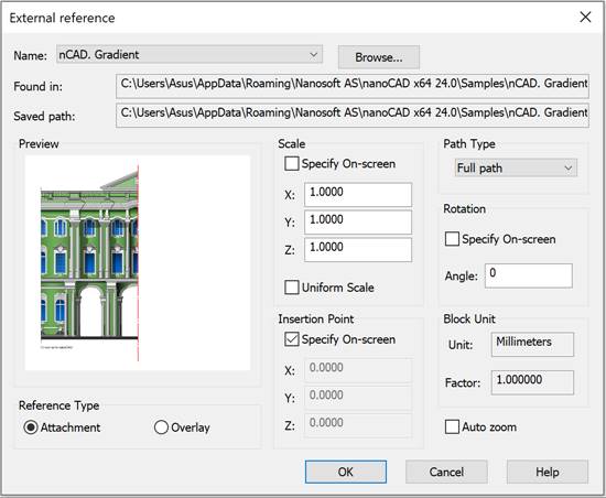
To insert an external reference into the drawing, specify the path and file name in the opened External Reference dialog box: To insert an external reference, the External Reference dialog box opens, which is a standard Windows file open dialog in which you should specify the path and file name to insert as an external reference. To specify several files at once for simultaneous insertion, select them with the CTRL or SHIFT.
|
|
Note |
|
In case of inserting multiple files, some insertion options will not be available. |

Select the necessary external reference and click Open. The External Reference dialog box will open.
|
|
Note |
|
In case you insert multiple files at once, many insertion parameters will not be available. |

|
Parameter |
Description |
|
Name: |
The list of the names of the external references inserted into the drawing. |
|
|
Opens the Open dialog box to choose files for the insertion of new references. |
|
Found in: |
Displays the file path where the external reference is to be found. |
|
Saved path: |
Displays the saved path of access to the external reference. |
|
Reference Type |
Attachment – enables an insertion mode, which loads and displays an external reference when the drawing containing it is inserted into another drawing as an external reference. Overlay – enables an insertion mode, which ignores the external reference and does not display when the drawing containing it is inserted into another drawing as an external reference. |
|
Path Type |
Selects the saved path type to the external reference: Full path Relative path No path |
|
Insertion Point |
Specify On-screen – enables/disables the mode for selecting a base point with the cursor on the screen after closing the dialog box. X: Y: Z: - enters the coordinates of the external reference insertion point |
|
Scale |
Specify On-Screen – enables/disables the mode for specifying the scale using the cursor on the screen after closing the dialog. X: Y: Z: – enters scaling factors for the X, Y, and Z axes. Uniform Scale – enables/disables the automatic application of the scale specified for the X axis to the Y and Z axes. |
|
Rotation |
Specify On-Screen – enables/disables the mode for specifying the external reference rotation angle using the cursor on the screen after closing the dialog. Angle: – enters the rotation angle for the inserted external reference. |
|
Block unit |
Unit: – displays information about the measurement units specified when creating the external reference. Factor: – displays the scale factor, calculated as the ratio of the external reference units to the drawing units. |
|
Auto Zoom |
Switches on/off the full screen mode of the inserted reference. |
