

 De
De  Es
Es  Fr
Fr  Pt
Pt 

-
-
-
-
-
-
-
-
-
-
-
-
-
-
-
-
-
-
-
-
-
-
-
-
-
-
-
-
-
-
-
-
-
-
-
-
-
Input Field Context Menu
-
-
-
-
-
-
-
-
-
-
-
-
-
-
-
-
-
-
Input Field Context Menu
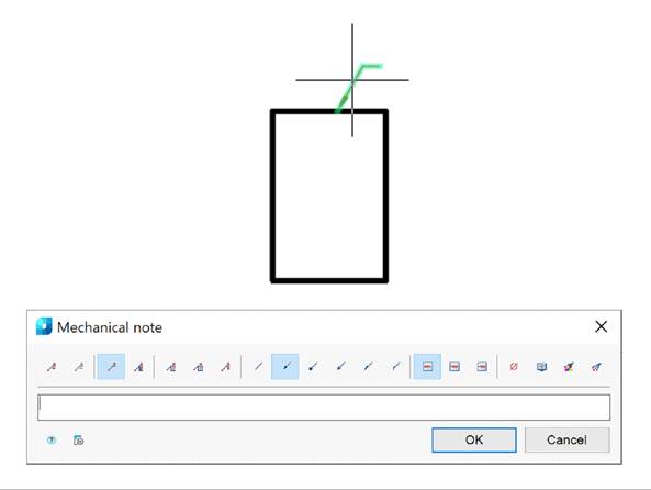
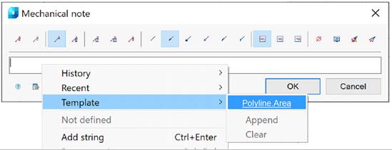
In the input fields of design elements, a context menu is available that allows you to insert certain values or objects. Example of the context menu of a mechanical note:
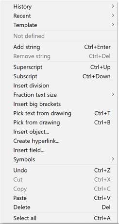
Context menu commands:
History – contains a list of the last entered values.
Recent – is a user-configurable list. After typing the desired text, you can add it to the frequently used list for quick access later.
Template – connects templates. Similar to the Recent command, it contains a list. You can add a new entry if the text contains a link to an object.
Add string – adds a string to the note text (a field for a new string appears in the dialog box).
Remove string – removes a string.
Superscript – inserts a superscript (combination CTRL+UP ARROW) .
Subscript – inserts a subscript (combination CTRL+DOWN ARROW).
Insert division – inserts fractional text.
Fraction text size – selects a fraction size option from the list: Default, Like the main text, One step less.
Insert big brackets – inserts round brackets.
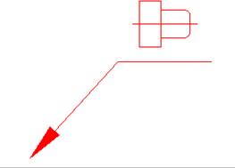
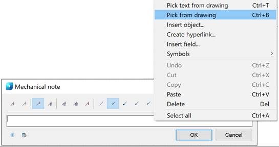
Pick text from drawing – inserts the text specified in the drawing into the field. If the original text is changed, the text of the universal callout will be updated automatically.
Pick from drawing – allows you to take data from the drawing and from the properties of objects.
Insert object... – nserts a graphic object instead of text while maintaining a dynamic link. As a result, an object with its own context menu will be inserted.
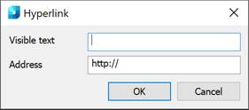
Create hyperlink... – creates a hyperlink to a file or page in the Internet. When you run the command, the Hyperlink dialog will open, where you should specify the visible text and address. As a result, an object will be inserted that has its own context menu. The link will be visible in the tooltip when you hover over the object.
Insert field… – inserts a field (FIELD command). As a result, an object will be inserted that has its own context menu. When you click on the field link, the visibility area will move to the linked object. You can update the data using the Update command.
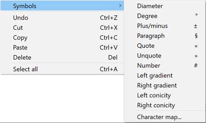
Symbols – inserts a standard symbol (degree, slope, etc.) or any symbol from the OS symbol table.
Undo – undoes the last action (CTRL+Z combination).
Cut, Copy, Paste – standard operations using the OS buffer.
Delete – deletes text from the input field.
Select all – selects all text in the input field (for example, for replacement).
Templates are used to create similar objects with the same properties.
Example of creating and using a template based on a note
1. Create a rectangle of arbitrary area. Assign a note to it and open the note editing dialog.
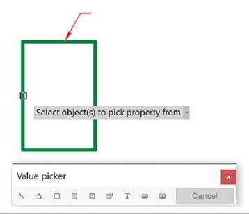
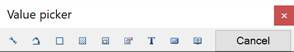
2. In the input field, open the context menu and select the Pick from drawing command. The Value picker dialog will open.
3. In the Value picker dialog, select the  Take from property command.
4. Select the rectangle and press Enter.
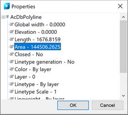
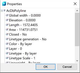
5. From the Properties window, select Area and click OK button.
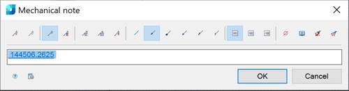
6. A link to the property (object area) has appeared in the note text.
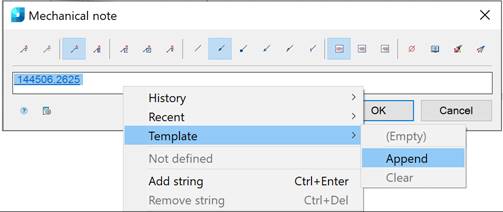
7. From the note’s input field, open the context menu and select the Templates – Append command.
8. Close the note editing dialog.
9. Construct a rectangle of arbitrary area. Assign a note to it and open the note editing dialog.
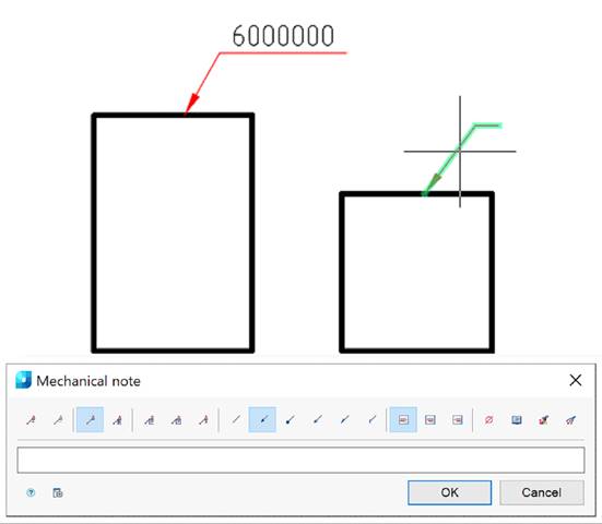
10. In the input field, open the context menu and select the Templates – Polyline.Area command.
11. Select the second rectangle to calculate the area. The area will be calculated automatically.
The Pick from Drawing context menu command opens the Value picker dialog, which allows you to copy values from drawing objects:
 Measure distance (Z) – takes a linear or diametric geometric dimension from the drawing. The command can be opened by pressing the Z key .
 Measure angle (X) – takes an angular dimension from the drawing. The command can be opened by pressing the X key .
 Measure perimeter (C) – takes the perimeter value of a closed line or the length of a broken line from the drawing. The command can be opened by pressing the C key .
 Measure area (V) – takes the area value of a closed contour from the drawing. The command can be opened by pressing the V key.
 Complex area (Shift+V) – takes the value of several areas of a closed contour from the drawing .
 Take from property (B) – takes the parameter values from the drawing object. The parameter is inserted while maintaining a dynamic link with the object. As a result, an object with its own context menu is inserted. When you change a part parameter, the line in the input field changes.
|
|
Note |
|
To insert static text, hold CTRL while selecting a parameter. |

 Take from text (N) – takes text from a drawing object.
 Calculate (M) – calculates a numerical value using the built-in nanoCAD calculator.
 Take from notes (,) – inserts text information from a notebook.
Cancel – cancels the command and returns to the previous menu.