

 De
De  Es
Es  Fr
Fr  Pt
Pt 

-
-
-
-
-
-
-
-
-
-
-
-
-
-
-
-
-
-
-
-
-
-
-
-
-
-
-
-
-
Diameter Dimensioning
-
-
-
-
-
-
-
-
-
-
-
-
-
-
-
-
-
-
-
-
-
-
-
-
-
-
Diameter Dimensioning
 Ribbon: Home, Annotate – Dimensions >
  Auto
Auto
Ribbon: Home, Annotate - Dimensions >  Diameter
Menu: Dimensions –  Diameter dimension
Toolbar: Utilities –
Context menu when calling any dimension: Diametral
 Command line: MDIMDIA
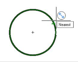
For dimensioning the diameter of a circle:
1. Place the cursor over the circle to show its dynamic highlighting. When setting a diameter dimension using the Auto command, an auxiliary marker  appears. Left click to confirm the dimensioning selection:
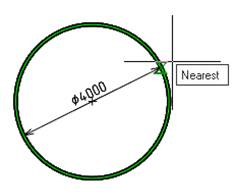
Choose the location of the dimension:
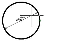
2. Left click to fix the chosen location:
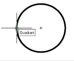
For dimensioning the diameter of a circle using characteristic points:
1. Turn on the Quadrant snap.
2. Start the Auto command.
3. Place the cursor over the circle to the first defined point. Left-click to select the end point of the first extension line of the dimension. Left click to confirm the dimensioning:
4. Move the cursor to the second characteristic point of the circle and left click to specify the endpoint of the second extension line of the dimension.
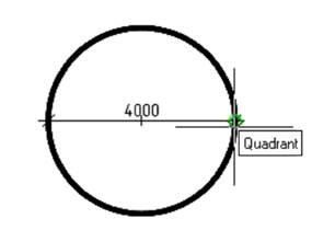
Move the cursor to display the auxiliary symbol: or
or  . Select the location of the dimension. Left-click to fix the selected position:
