De
De  Es
Es  Fr
Fr  Pt
Pt 

-
-
-
-
-
-
-
-
-
-
-
-
-
-
-
-
-
-
-
-
-
-
-
-
-
-
-
-
-
Angular Dimensions
-
-
-
-
-
-
-
-
-
-
-
-
-
-
-
-
-
-
-
-
-
-
-
-
-
-
Angular Dimensions
 Ribbon: Home, Annotate - Dimensions >
  Auto
Auto
Ribbon: Home, Annotate – Dimensions >  Angular
Menu: Dimensions –  Angle dimension
Toolbar: Utilities –
Context menu when calling any dimension: anguLar
 Command line: MDIMANG
To draw the angle between two segments:
1. Place the cursor over one of the segments to show its dynamic highlighting. When you set an angular dimension using the Auto command, an auxiliary marker  appears. Left click to confirm the selection:
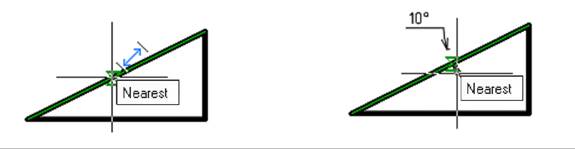
2. Place the cursor over the second segment to show its dynamic highlighting. When you set an angular dimension using the Auto command, an auxiliary marker  appears. Left click to confirm the dimensioning:
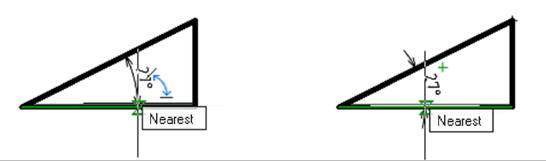
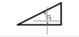
Choose the location of the dimension:
3. Left click to fix the selected location:
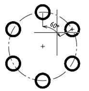
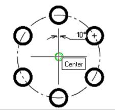
For dimensioning the angular dimension using characteristic points:
1. Place the cursor over the circle on which holes are located and specify the center of this circle (vertex of angle):
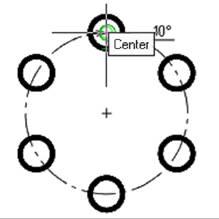
2. Specify the second point of the angular dimension (first hole center):
3. Specify the third point of the angular dimension (second hole center):
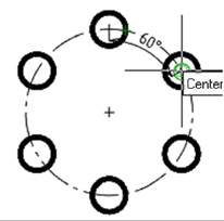
4. Select the location of the dimension. Left-click to fix the selected position: