De
De  Es
Es  Fr
Fr  Pt
Pt 

Point Clouds View Mode
 Ribbon: Point Clouds > Settings >
  View Mode
Menu: Point Clouds >  View Mode
Toolbar: Point Clouds > View Mode
Functional bar Properties – Visualization section – View Mode parameter>  button
 Command line: NPC_VIEWMODE
The command opens the View Mode toolbar that allows you to stylize a point cloud in accordance with the values of these or those attributes of this cloud. In fact, the command paints each cloud point in accordance with the attribute value in this point. The user selects the attribute by stylize by. In case the necessary attributes are present in the cloud, stylization is possible by:
· color;
· intensity;
· class;
· echo number;
· source ID.
Also, you can color point cloud by selected color or cloud elevation (along the Z axis).
Options:
|
|
When enabled, the selected cloud is not highlighted. |
|
|
The buttons switch the display of the recoloring result after the Apply changes button is pressed. |
|
|
The displayed size of a cloud point on the screen in pixels. The size of the deviation vectors and normals also depends on this parameter.
|
|
|
A drop-down list of cloud attributes available for stylization. The number of attributes in the list depends on which of them were imported together with the cloud from the scan file.
|
|
|
The number of intervals of the same color into which the entire measurement will be divided during coloring. This field is available when coloring by height, intensity, or deviation. |



It is possible to disable several forms by selecting them first using the Shift key.
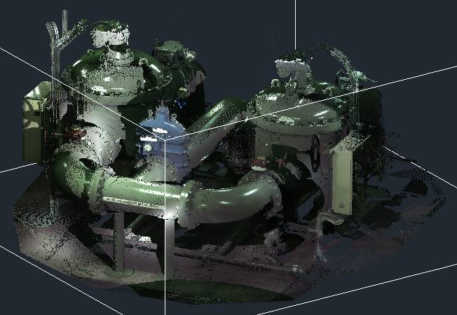
Stylizes the cloud to match the color of the points in the original scan file.
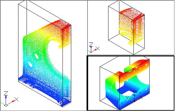
Stylizes depending on the Z coordinate value at each point of the cloud.
|
|
|
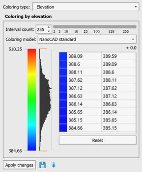
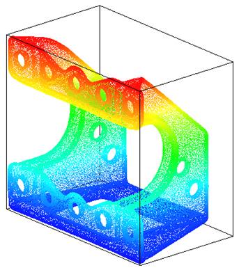
|
|
Cloud view mode based on the intensity of the reflected pulse (Intensity attribute).
|
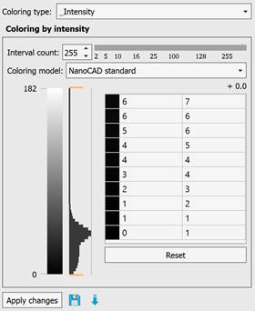
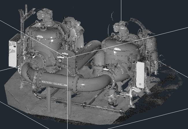
|
|
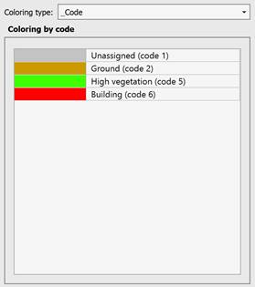
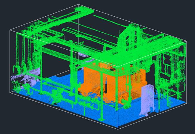
As a result of the final processing of the scan results, cloud points can be classified in a certain way, for example: ground, vegetation, buildings. This display style allows you to color the cloud according to the standard LAS classification or according to a user-created classification.
|
|
|
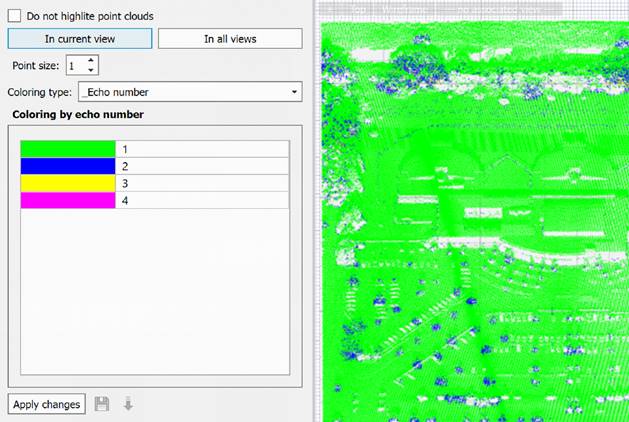
Color a cloud according to echo number of laser ray obtained as a result of scan.
|
|
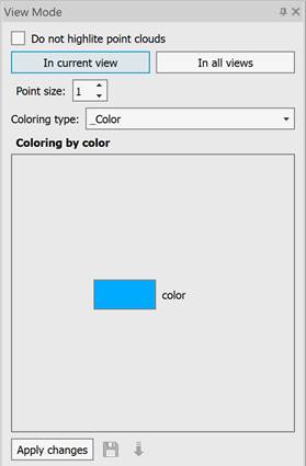
Coloring all cloud points by any selected color.
|
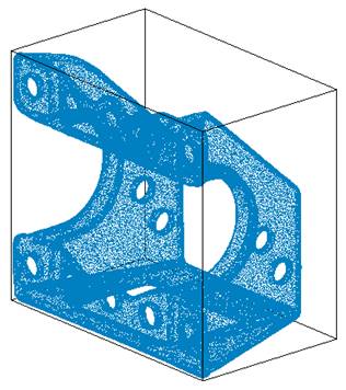
|
|
As a result of each scan, cloud points are assigned a unique identifier. One cloud can be formed as a result of several scans of the same object from different points. This type allows you to color cloud points depending on the scanning source ID. The color of the points for each scanning source is selected automatically by the program.
|
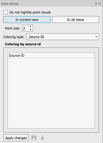
Renders the direction of cloud point normals (Normal attribute), if present in the cloud. It is possible both to color the points depending on the normal direction, and to directly display the normal vectors.
Cloud points are colored according to the direction of their normals.
|
|
Normals are created by cloud triangulation, shape detection in a cloud, fitting vector primitives (commands available in the 3DScan application). Normals may not always be calculated correctly. In this case, it is recommended to recalculate the normals (reorder them). When the Half-space normals box is checked, all collinear normal vectors are displayed in the same color. This coloring does not distinguish between normals pointing in exactly opposite directions. At that, they are assigned a color equal to the interpolation of colors of the axes of the current UCS. Points with normals collinear to a specific coordinate axis will have the color of that axis. |
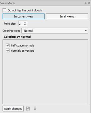

You can check the Normals as vectors box to display the normal vectors, and not just color the points of the cloud according to the directions of the normals. The size of the vectors on the screen depends on the size of the cloud point (Point size field). Normal vectors are only displayed when using DirectX as a hardware graphics accelerator.
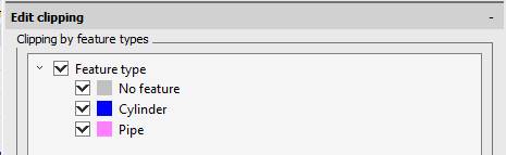
The Feature type and Feature coloring become available for point clouds, in which features have been recognized by geometry search commands (pipelines, pipeline components, planes, plane element). These coloring types are designed to visualize such features in a cloud.


The Deviation coloring is designed to visualize the deviations of scanned points from the specified geometry.
To select a boundary, click the boundary value. The parameter will enter editing mode, then specify the new boundary value.
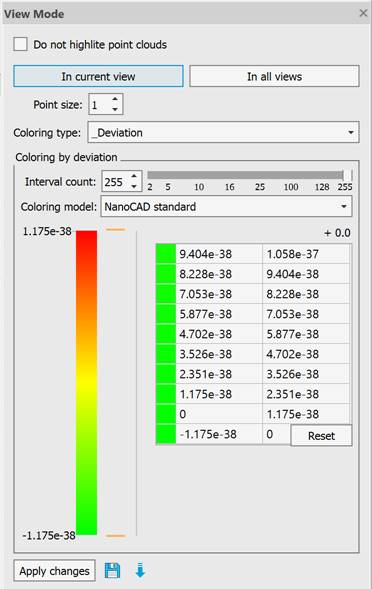
Coloring the cloud for which the fractal dimension has been calculated.
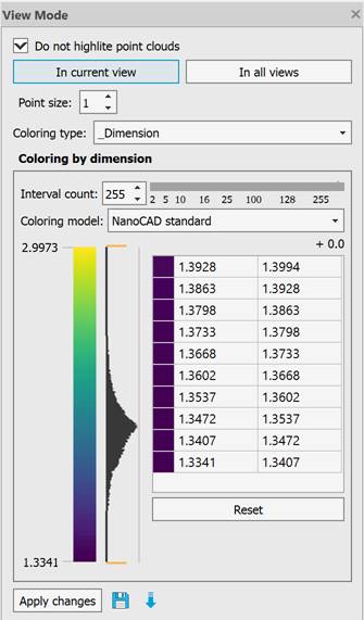
To select a boundary, click the mouse on the boundary value; the parameter will switch to editing mode, then specify a new boundary value.
When choosing cloud styling by Height, Intensity and Fractal dimension, it is possible to save custom color palettes and intensity settings to a XML file and import XML color palette files.
At the bottom of the panel is the Clipping section, which handles data segmentation based on geometric and attribute-based criteria.
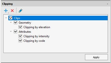
Geometric criteria:
· by named views
· by code
· by features
· by feature types
· by echo number
· by geometry
Attribute-based criteria (if the point cloud has attributes):
· intensity
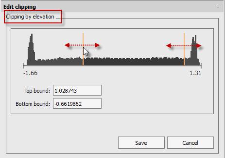
· elevation
· source ID
· by spatial dimension
· by deviations
· by fractal dimension
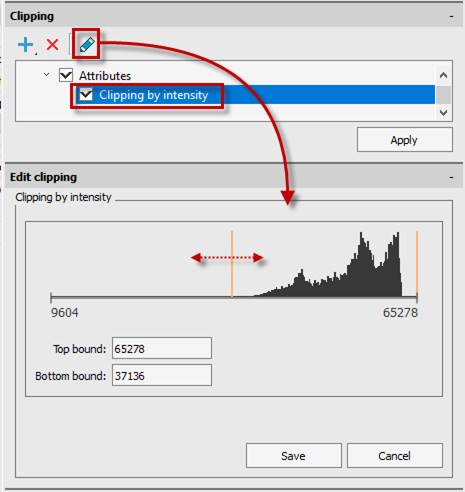
Most clipping settings can be edited using the  button.
The Edit Clipping tool, located at the bottom of the panel, allows you to modify the parameters of existing clips for point clouds.
Some types of geometric clips:
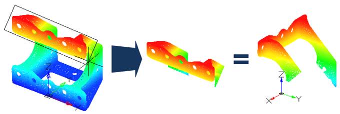
· Rectangular clip (you can change the coordinates of the base point and normal, as well as the rectangle’s parameters; you can also invert the clip and select the rectangle type)
· Sphere clipping (you can change the coordinates of the center point and the radius of the sphere, and invert the clipping)
· Cylinder clipping (you can change the coordinates of the base point and the normal, the height and radius of the cylinder, invert the clipping, and select the type of cylinder)