
 De
De  Es
Es  Fr
Fr  Pt
Pt 

-
-
-
-
-
-
-
-
-
-
-
Adjustment of Point Clouds Using a Trajectory
-
-
-
-
-
-
-
-
-
-
Adjustment of Point Clouds Using a Trajectory
 Ribbon: Point Clouds > Aerial Laser Scanning >
  Adjust point clouds ujsing a trajectory
Menu: Point Clouds > ALS >  Adjust point clouds ujsing a trajectory
Toolbar: ALS >  Adjust point clouds ujsing a trajectory
 Command line: PC_CLOUDS_ADJUST_WITH_TRAJECTORY
The command is designed to correct the mutual displacement of point clouds. Using the trajectory allows for the elimination of systematic distortions in the direction and coordinates of the emission point.
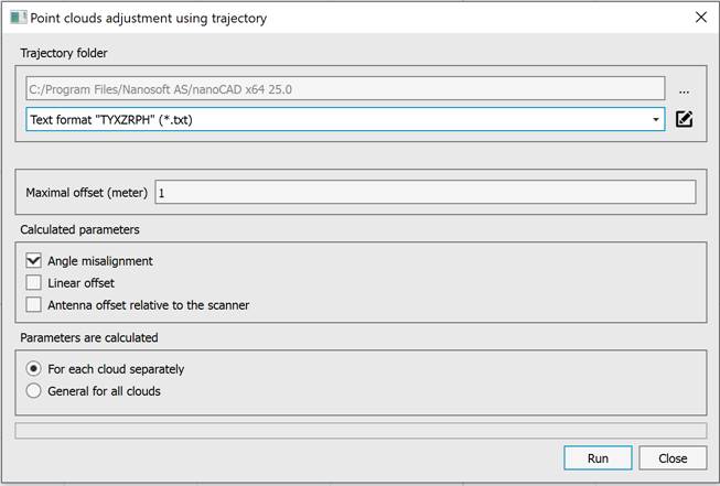
For the command to work it is necessary to:
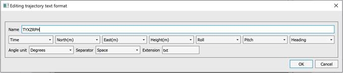
1. Select a folder containing trajectory files in TRJ format or text format. To configure the text format, click the button and edit the list of text trajectory formats. If necessary, you can add a new format by specifying its name, the sequence of fields in the file, units of angles, separator, and file extension.
2. Enter the maximum discrepancy between the point clouds in meters.
3. Select the calculated systematic distortions in the Calculated parameters section:
- Angle misalighnment – misalignment of the angles of the inertial system and the scanner;
- Linear offset – linear displacement of the emission points in the ground coordinate system;
- Antenna offset relative to the scanner – antenna offset relative to the scanner in the aircraft coordinate system.
4. In the Parameters are calculated section, select one of the options – For each cloud separately or General for all clouds. Calculating the parameters separately for each cloud may reduce discrepancies. If you calculate general parameters for all clouds, the calculated parameters can be used later to eliminate offsets during the cloud loading stage. To do this, enable the Save calculated parameters to calibration file mode and select the file.
|
|
Note |
|
For the command to work, the drawing should contain two point clouds. |
