-
-
-
-
-
-
-
-
-
-
-
-
-
-
-
-
-
-
-
Surface Difference
-
-
Surface Difference
 Ribbon: 3DScan > Texturing and Calculations >
  Surface Difference
 Menu: 3DScan >Calculation >
  Surface Difference
 Toolbar: Texturing and Calculation >
  Surface Difference
 Command line: PC_HEIGHT_DIFFERENCE
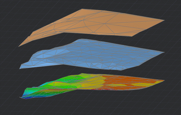
The Surface Difference command creates a new surface by subtracting one surface from another by height.

The source surfaces can be a SubDMesh or a PolyfaceMesh.
The resulting surface is obtained by combining the points of the first and second surfaces, preserving their X and Y coordinates. The Z coordinate is calculated as Z of the first plane minus Z of the second plane. Since the X and Y coordinates of the points of the first and second surfaces do not coincide, then in fact the Z coordinate of the points of the new surface is calculated as the difference between the Z coordinates of the existing points of one or another surface and the Z coordinates of the intersection of perpendiculars from these points with the other surface.
The command has no options. To perform it, you only need to specify the source mesh.
The command is applicable to obtain a height map with a legend: the resulting surface can be colored by height using the Coloring the Mesh by Height command and generate a legend using the Formation of a Legend command.


 De
De  Es
Es  Fr
Fr  Pt
Pt 
