Searching for Planes in the Point Cloud
 Ribbon: 3DScan – Features >
  Searching for Planes in the Point Cloud
 Menu: 3DScan – Features >
  Searching for Planes in the Point Cloud
 Toolbar: Features 3DScan >
  Searching for Planes in the Point Cloud
 Command line: PC_PLANAR_FEATURES
The command searches for the following geometry in the point cloud:
· Planes;
· Edges (intersection of two planes). To search for edges, enable the Edge Detection parameter.
Display of Detected Features
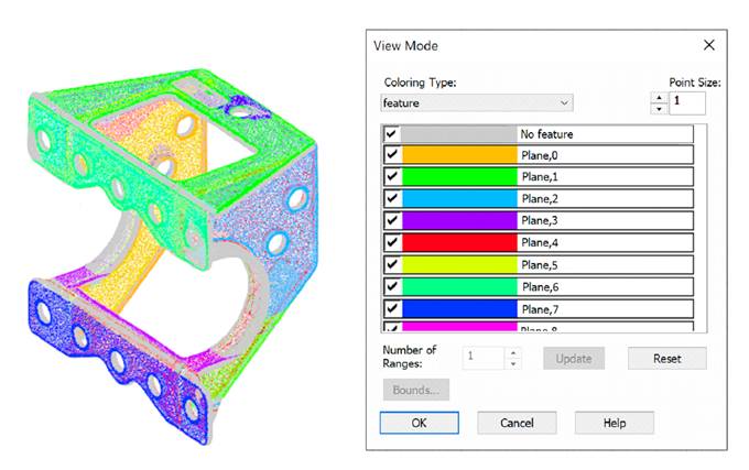
To display recognized features, two types of coloring are created: Feature type and Feature, which is set as current. In the View Mode dialog, you can set these coloring types and disable the display of unnecessary elements. For example, unrecognized areas of the cloud, edges, planes or any specific feature.
Coloring by feature type:

Coloring by feature:

In addition, it is possible to create classes based on the detected Feature types (the Save type to class option).
Features recognition
The function of planes recognition in point clouds is the combination of two algorithms: stochastic Hough algorithm and one-point identification of planes by local normals.
The recognition process may take a long time, depending on the size of the cloud and the set parameter values.
|
|
Note |
|
Recognition of a large number of forms on large and saturated clouds is highly dependent on system performance and can take a significant amount of time. Before using the command, it is recommended to display in the active viewport only that part of the cloud where recognition should be performed. To do this, use the cloud clipping and sectioning commands. |
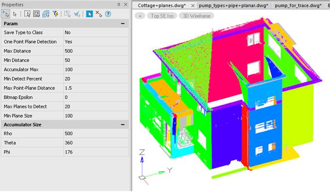
Immediately after the start, the command creates the point normals (if they are absent in the cloud) and reorients them if necessary. Then the recognition options are displayed in the Properties bar for correction and approval.


The command options are set in the Properties bar.
Options:
|
Save Type to Class |
Whether to create classes based on the detected feature types: · Yes, – the command will create new point classes with names corresponding to the recognized feature types and classify the cloud points. · No – classes will not be created, points will not be classified. |
|
One Point Plane Detection
|
Selection of the recognition algorithm. If No, then a 3-points cells construction procedure is used, which is split the point cloud during the planes recognition. The Max Distance and Min Distance options set the minimum and maximum size for such cells. In addition to the 3-point procedure, a 1-point procedure is used that creates cells by random point and its normal. The required planes are specified by the point p on the plane, the normal vector n, perpendicular to the plane, and ρ - distance from the origin. This method works faster, does not require the parameters of the minimum and maximum cell edges (Max Distance and Min Distance), but it may not find shapes with a very noisy normal and acceptable tolerance. |
|
Max Distance |
The maximum allowable length of the edge of the cell, into which the cloud is split during the plane recognition. The size of the cells must be such that the smallest recognizable plane contains at least several cells. |
|
Min Distance |
The minimum allowable length of the edge of the cell, into which the cloud is split during the plane recognition. |
|
Accumulator Max |
The threshold value in the accumulator, above which the plane is recognized. The larger the value, the more reliably the plane is recognized, but the recognition time increases. |
|
Min Detect Percent |
The minimum acceptable percentage of unrecognized cloud points. |
|
Max Point-Plane Distance |
Maximum deviation of point position in the plane from ideal. In other words, there is a spread of coordinates that may be neglected to suggest that the points belong to the same line, surface, edge, etc. The tolerance should be greater the worse objects' surfaces and edges are expressed. At the same time, if the threshold distance increases too much, the risk of inaccurate plane placement increases as well as the chance of recognition of the plane in the place where it does not exist. |
|
Bitmap Epsilon |
The maximum distance of a point from a plane at which the point can still be considered to belong to the plane. In other words, there is a spread of coordinates you may neglect to consider that the points belong to the same line, surface, edge, etc. The less accurate the scan is, the greater the tolerance. 0 has a special meaning to indicate that the connectivity tolerance is calculated automatically. This value is set by default. |
|
Max Planes to Detect |
The maximum number of planes that can be recognized in the cloud. The larger this value, the longer the recognition process. It is always possible to call a command again with a new value for the number of planes; in this case, there will be planes that were not found on previous calls of the command. |
|
Min Plane Size |
The minimum number of points that make up the surface. Should be set to the number of points in the smallest plane in the cloud that should be recognized. |
|
Edge detection |
Search for Edge type features. When the parameter is disabled, only the search for planes will be performed. |

|
Accumulator Size |
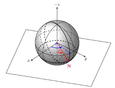
Dimensional characteristics of the cells accumulator. The desired planes are specified by a point p on the plane, a normal vector n perpendicular to the plane, and ρ - the distance from the origin |
|
Rho (r) |
Normal vector length (N) - distance from a point on the plane to the origin |
|
Theta (q) |
The angle of the normal vector in the XY plane |
|
Phi (j) |
angle between the XY plane and the normal vector in the Z direction |
Command prompts:
|
Apply changes [Yes/No/ |
Yes – the command will be performed taking into account the settings changes made by the user in the current command session. No – the command will be performed with the settings that were displayed immediately after the command was launched. saveDefault - the settings will be saved in the registry, and subsequent drawings will use the parameters from the registry. Scalelinear1000 - scales the parameters by 1000. scaleLinear0.001 - scales the parameters by 0.001. scalelinearAny - scales the parameters by the entered value. |


 De
De  Es
Es  Fr
Fr  Pt
Pt 

