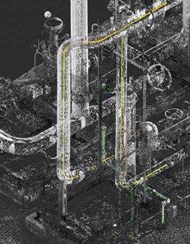
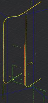
Searching for Pipes in Point Cloud
 Ribbon: 3DScan – Features >
  Searching for Pipes in the Point Cloud
 Menu: 3DScan – Features >
  Searching for Pipes in the Point Cloud
 Toolbar: Features 3DScan >
  Searching for Pipes in the Point Cloud
 Command line: PC_PIPE_FEATURES
Search for pipes in the point cloud. The command tries to recognize pipe and pipeline features (straight sections, transitions, elbows, T-pipes, flanges) based on the specified parameters. Straight and curved sections are recognized, and a parametric model is built.
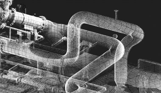
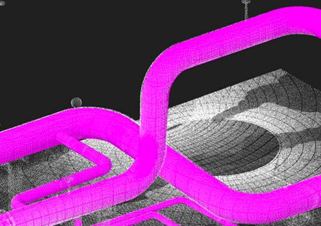
In the process of feature recognition, cloud points are typified (divided) into unrecognized points, cylinder points, pipe points: straight sections, curved sections and sections with a changed diameter.
The command recognizes the following features:
· Cylinder;
· Pipe (strait);
· Pipe (diam change);
· Pipe (bend).
Displaying detected features
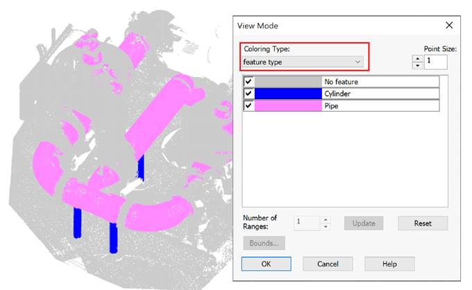
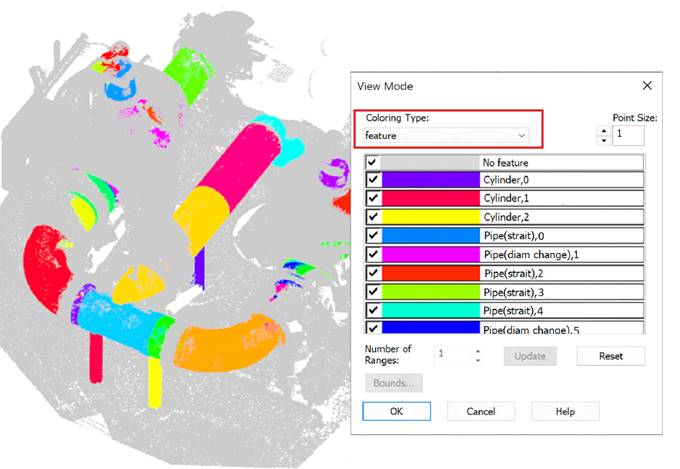
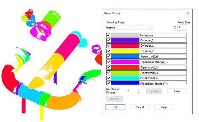
To display recognized features, two types of coloring are created: Feature Type and Feature, which is set as current. In the View Mode dialog, you can set these coloring types and disable the display of unnecessary elements. For example, unrecognized sections, straight pipes, bends or selectively a specific feature.
Coloring by feature type:
Coloring by feature:
Disabling the display of points outside of recognized geometry:
Displaying only bends and pipes with changing diameter:
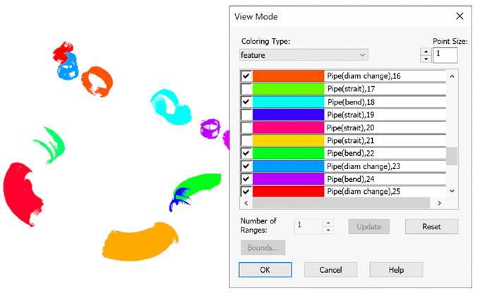
It is possible to switch to another coloring type. In this case, only the points of not disabled elements continue to be displayed:
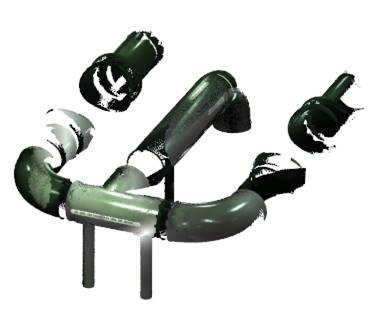
In addition, it is possible to create classes based on the detected Feature Types (the Save type to class parameter).
Feature recognition
The recognition process can take a long time, It depends on the size of the cloud and the specified parameter values.
|
|
Note |
|
Recognition of a large number of forms on large and saturated clouds is highly dependent on system performance and can take a significant amount of time. Before using the command, it is recommended to display in the active viewport only that part of the cloud where recognition should be performed. To do this, use the cloud clipping and sectioning commands. |
The pipe searching command is designed to be easy to run iteratively. The command works only on the part of the cloud that is visible on the screen at the moment, i.e. takes into account the views, sections and clippings of clouds. In addition, the recognition only takes into account those points that were not previously recognized as belonging to the geometry. Thus, it is possible to refine the recognition results by going to more accurately segmented parts of the cloud and changing the options.
Immediately after the start, the command creates the point normals (if they are absent in the cloud) and reorients them if necessary. Then the recognition options are displayed in the Properties bar for correction and approval.
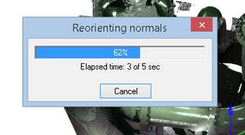
The command options are set in the Properties bar.
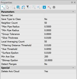
Options:
Recognition options:
|
Named Set |
A set of named recognition settings that can be quickly switched. |
|
Save Type to Class |
Whether to create classes based on the detected feature types (Feature type coloring type): · Yes – the command will create new point classes with names corresponding to the recognized feature types and classify the cloud points. · No – classes will not be created. Points will not be classified. |
|
Max Pipe Radius |
The maximum radius of pipes in the drawing units for which recognition should be performed. This parameter allows you to exclude flat areas and equipment with a large radius from the recognition process. Any plane with a certain error can be considered a part of a cylinder of a huge radius. The parameter was introduced in order to exclude flat areas of scanned surfaces from the recognition process. |
|
Min Pipe Radius |
The minimum radius of pipes in drawing units for which recognition should be performed. |
|
Group Tolerance |
The size of the conditional cell. For large clouds, the recognition time can be unacceptably long. To speed it up, the number of points under consideration is reduced by averaging the coordinates and attributes in cubic cells of the specified size. The larger the cell size, the fewer points are taken into consideration and the higher the recognition rate will be. If value = 0, grouping is not performed (disabled). |
|
Neighbor Count |
The number of neighbors for estimating the position of the section when calculating the center point. Typical value is 50-150. The larger the value, the more accurately the position of the axes is calculated, but the longer the calculation time. It is recommended to increase the value for noisy pipes or high density of points on the pipe surface. |
|
Slice Thickness |
The thickness of the pipe section to estimate the radius and location of the pipe. Increasing this parameter increases both the accuracy of the determination and the processing time. The value should be comparable to the radius of the pipe, increasing the value too much can degrade accuracy, especially on curved segments. |
Parameters used for pipe axis points:
|
Local Averaging Count |
The number of neighbors specified in this parameter is taken for each point of the axis cloud. The position and direction of the pipe axis are calculated from the adjacent points. |
|
Filtering Distance Threshold |
If the potential point of the axis is at a distance greater than this parameter, it is rejected. The higher the parameter value, the more noisy the axes are. However, when this parameter tends to zero, the number of points at the output decreases, which means the probability of successful recognition. The optimal value is determined by trial and error. |
Parameters used for vectorization:
|
Axe Threshold |
Accuracy of determining the axes of pipelines. The smaller this parameter, the closer the axes are to the real position, but the larger the number of short sections approximating the real pipeline. |
|
Surface Epsilon |
Pipeline surface tolerance, which determines whether a point belongs to a pipe. The more noisy the original data, the higher the tolerance value should be. |
|
Min Axe Size |
The minimum number of axis points that make up a piping element, such as a bend or pipe section. |
Special:
|
Delete Axis Cloud |
Axis clouds are created during pipe recognition. The parameter allows you to leave such clouds in the drawing.
However, you can create pipeline routes in the form of a 3D polyline using the Creating a Pipeline Route command. |
Command prompts:
|
Apply changes [Yes/No/ |
Yes – the command will be performed taking into account the settings changes made by the user in the current command session. No – the command will be performed with the settings that were displayed immediately after the command was launched. saveDefault - the settings will be saved in the registry, and subsequent drawings will use the parameters from the registry. Scalelinear1000 - scales the parameters by 1000. scaleLinear0.001 - scales the parameters by 0.001. scalelinearAny - scales the parameters by the entered value. |


 De
De  Es
Es  Fr
Fr  Pt
Pt 


