Search for Key Lines in the Point Cloud
 Ribbon: 3DScan > Meshes >
  Search for Key Lines in the Point Cloud
 Menu: 3DScan > Meshes >
  Search for Key Lines in the Point Cloud
 Toolbar: Meshes 3DScan >
  Search for Key Lines in the Point Cloud
 Command line: PC_KEY_LINES
The command is searching for key lines such as thalwegs, edges, etc. on the surface of a point cloud.

Parameters:
There are two parameters that need to be configured first: Resolution and Isolation Distance. The rest can be left at default values for the first time, since they do not depend on the drawing units.
Resolution
The main parameter. Determines the degree of detail, such as how large the radius of a point’s neighborhood will be to determine if it has an inflection point. Also defines the step between points of the resulting polylines.
The parameter is measured in drawing units. Usually, the optimal value is 4-5 meters.
If the value of the Resolution parameter is too small (high resolution), the slightest kinks in the relief will be detected, but smooth kinks, which are more important from the point of view of key relief lines, may not be detected. So, if a lot of scattered small lines are created, most likely the value of the Resolution parameter is too low.
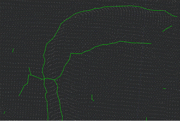
If the parameter value is too high, the opposite picture results: there are few lines and they are very inaccurate. If at the same time the Isolation Distance parameter, which is responsible for the lines integrity is set twice as large as the Resolution parameter value, then there will be even fewer lines and they will fall apart, and if you set it much more, the lines will stick together where they are not needed. The example below shows exactly this situation: too high value for the Resolution parameter with a large value for the Isolation Distance parameter.
Key Points Percent
This parameter determines how sharp corners are considered bends. You should increase the parameter value if you want to recognize more bends, and decrease it to reduce the number of them and take into account only the sharpest corners. This parameter is also related to the Resolution parameter, since the bend is considered to be within a sphere of radius determined by the resolution. The parameter values vary from 0 to 1. As a rule, the optimal value is 0.075.
Isolation Distance
The value of this parameter is also specified in drawing units. The Isolation Distance parameter is closely related to the Resolution parameter. It affects how lines are separated from one another. If the values are too high, the lines will stick together; if the values are too low, the lines will fall apart. The value of the Isolation distance parameter must be greater than the value of the Resolution parameter, otherwise nothing will be detected. The optimal value is three to five times greater than the Resolution.
Smoothing Pass-band and Smoothing Iterations
Smoothing Pass-band and Smoothing Iterations are the line smoothing parameters. It makes sense to change them only if the lines seem zigzag and need to be smoothed out even more. In this case, you can try increasing the number of iterations. In most cases, there is no need to change parameter values. The values of the Smoothing Pass-band parameter range from 0 to 2, lower values correspond to more smoothing.
The example below shows the lines obtained with only one iteration. They are practically without smoothing, you can see that they are going a little zigzag.


 De
De  Es
Es  Fr
Fr  Pt
Pt 
