Registration by Pairs of Corresponding Points
 Ribbon: Point Clouds – Point Cloud >
  By Pairs of Corresponding Points
 Menu: Point Clouds – Registration >
  By Pairs of Corresponding Points
 Toolbar: nanoCAD Point Clouds >
  By Pairs of Corresponding Points
 Command line: PC_REGISTRATION_MANUAL
The command allows you to perform registration of clouds not just by their download from an external file (as it happens when using Import reference points and Registration by reference points commands), but also by specifying pairs of corresponding points manually on the screen.
You can combine both the clouds themselves and clouds with various vector objects (for example, reference models).

Specifying base and secondary point clouds
After running the command, specify consistently two groups of point clouds:
1. Base point clouds – a point cloud whose coordinates will be taken as base ones, and to which secondary point clouds will be adjusted. Base reference points will be specified on base point clouds. At the end of selection, press Enter;
2. Secondary point clouds – a point cloud or several point cloud, which will be adjusted to base ones after registration. At the end of selection, press Enter.
After that the Registration by points toolbar will be displayed on the screen, and the work space will be divided into two viewports containing the selected clouds: the base clouds in the left viewport, the secondary in the right.
|
|
Note |
|
You can specify only one Base point cloud and one Secondary point cloud. |
Entering reference points
Reference points can be specified in two ways:
1. Download from an external file with commands Open file of base markers and Open file of secondary markers from the menu of  button;
2. Run the command  Add point and manually specify base and secondary relevant points on the screen.
Manually the points are added in pairs, in the left viewport and the right viewport by turns, automatically forming the relevance of reference points.
To be able to specify the reference points on the cloud, use the following snap modes:
· Snap to points of point clouds;
· Object snap to a knot and/or to the nearest point.
If Object snap and its Node or Nearestmodes were turned off, and snapping to the point cloud (SwitchPCSnapON) was also turned off, then when you start adding points, these snaps will be turned on. Upon completion of adding points, snap modes will return to the state that was configured by the user before adding points
After specifying the base reference point in the left viewport, its coordinates are displayed in the left part of the table. The right viewport becomes active, in which it is necessary to specify the secondary reference point, which is associated with the previous one.
The points name is formed automatically: Point1, Point2, etc. It can be changed at any time.
Upon completion of specifying one pair of relevant points, the next pair is specified. To end to specify, press Esc.
Ideally, combining requires a minimum of three pairs of points. After specifying the third pair of points, the preliminary combining mechanism is activated:
· The discrepancy is automatically calculated for all pairs of points in the table (Discrepancy column). Discrepancy (error) is the main parameter by which one can judge the quality of future registration. The discrepancy value is calculated for each pair of corresponding reference points. Pairs of points with large discrepancy values are highlighted in yellow in the table, and those with values outside the acceptable range are highlighted in red.
· The display of base and secondary objects (clouds) begins to synchronize in the right and left viewports. When you move, rotate, or scale a view in one viewport, the view synchronously moves, rotates, and scales in another viewport.
You can configure columns in the table in the dialog box opened by the  Show setup dialog command.
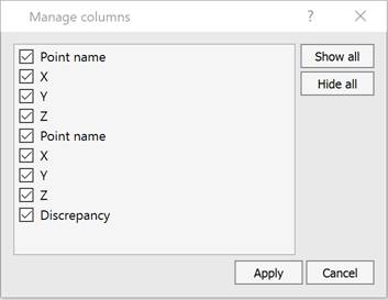
If the mode  Enable marker highlighting is enabled, then the marker of the point selected in the table is highlighted on the screen changing its color to blue. For automatic zoom in and pan to the point selected in the table, it is necessary to turn on
  Enable pan when selected mode.
It is possible to change the position of a marker of already specified point by the command  Change marker position.
The  Delete selected points command deletes the pair of relevant points selected in the table.
To scale clouds during calculations ( Solve button) or during registration (
 Apply transformation button), select the
  Enable scaling mode. Otherwise the transformation will only involve move and rotation.
Calculation
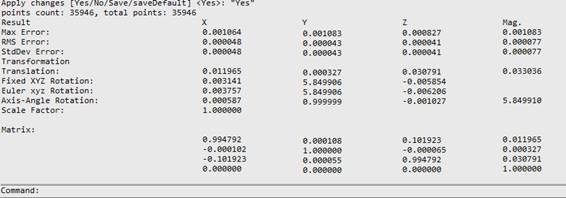
Before registration (alignment), it can be useful to perform a preliminary calculation of the transformation parameters. The  Solve command performs a preliminary alignment based on the specified pairs of points, displaying the transformation values in the command line.
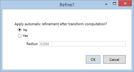
Before calculation, a dialog appears with a prompt whether it is necessary to carry out a detailed approximation after the main alignment (the detailed approximation algorithm is used in the Combining a Cloud with a Model command).
|
Apply automatic refinement after transform computation? |
Complete combination occurs in two stages. At the first stage, an initial (rough) approximation is carried out. Then, if necessary, more detailed combining is carried out. · No – carry out only the initial approximation, without detailed alignment. · Yes – carry out the initial approximation followed by detailed alignment. |
|
Radius |
The distance within which the geometry is considered for comparison. If all points of the geometry with which we are comparing lie at a distance greater than the radius, then the deviation is considered infinite. Such points are drawn in black. If there are points in the compared geometry that lie at a distance less than the radius, the minimum distance is taken as the deviation. |
Registration
Registration is performed by the  Apply transformation command.
After registration is completed, the base and secondary clouds or objects are combined, the Points registration bar is closed, the command completes its work, and the workspace returns to its original form.
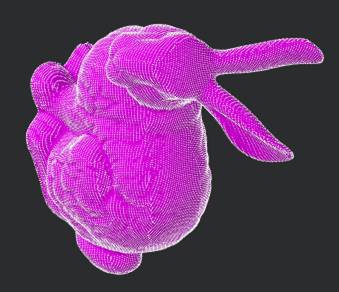
Registration Information
You can view the report and, if necessary, save it to HTML file using the Registration information command  .
.
Auto Point Clouds Registration
 Ribbon: Point Clouds > Point Cloud >
  Auto point clouds registration
 Menu: Point Clouds > Registration >
  Auto point clouds registration
 Toolbar: Point Clouds 3DScan >
 Command line: PC_REGISTRATION_AUTO
This command allows for automatic registration (stitching) of point clouds without the use of reference points.
For automatic registration, select two point clouds to be aligned, then specify the one relative to which the registration will be performed. If the automatic mode is selected, the user’s actions end there; the neural network will automatically determine the preferred algorithm based on the images, and other parameters will also be calculated. An important condition is that the point clouds should have calculated normals; without this, the automatic mode does not work.
The command parameters are set in the Properties bar.
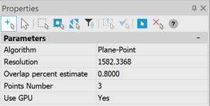
|
Algorithm |
Selects the registration algorithm. |
|
Resolution |
Indicates how often (with what step) points are selected on the cloud for registration. |
|
Overlap percent estimate |
Shows what portion of the clouds is expected to already overlap before registration. |
|
Points Number |
The number of points in each iteration of the registration algorithm to find the next approximation. |
|
Use GPU |
Use of hardware capabilities supporting DirectX 11, if available. It is not recommended to disable this option. |


 De
De  Es
Es  Fr
Fr  Pt
Pt 

