De
De  Es
Es  Fr
Fr  Pt
Pt 

Recognition Settings
 Ribbon: 3DScan – Features >
  Recognition Parameters…
Menu: 3DScan – Vectorization >  Recognition Parameters…
Toolbar: Features 3DScan > Recognition Parameters
 Command line: PC_R2V_OPTIONS
|
|
Note |
|
A drawing should contain at least onr point cloud for this command to run. |

Dialog allows you to set options for creating and vectorizing sections with Layer-by-layer vectorization command.
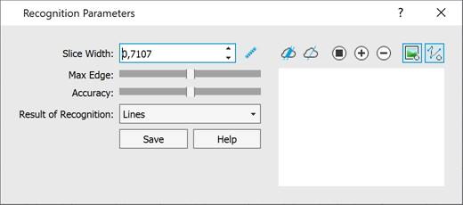
The dialog displays and changes the recognition settings for clouds of the current document. The settings are saved directly in the document itself. When switching to another drawing, the dialog will display the cloud recognition settings for this document. The dialog will be automatically hidden when switching to a document without point clouds and re-displayed when switching to a document with clouds.
Procedure to configure recognition:
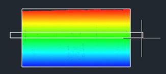
First of all, click the  Reinitialize section and it’s params button to specify position and width of section.
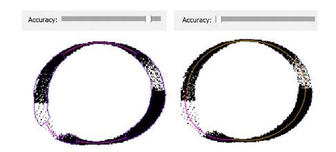
Preview displays bitonal raster image. It is changed every time when options changed. Thin color lines display vectorized data.
The sections displayed in the preview window of this dialog are used only for setting the recognition parameters and are not taken into account by the Layer-by-layer vectorization command, which builds a set of sections relative to the UCS or the direction of the current view.
Click the  Create section button to set position of section. Set the section width on the screen by using the
  button, or enter exact value of width in the Slice Width field.
Recognition options:
|
Slice Width |
The width of cloud cross-sections (layers) to be vectorized. Set the slice width (in the drawing units) or click the Excessive section width can lead to noise and thickening of contours, to the appearance of unnecessary contours and distortion of the topology, as a result of excess cloud points getting into the section. Insufficient width makes contours thin and discontinuous due to the lack of cloud points falling into the section.
|
|
Maximum Edge Length |
The maximum length of a raster line that should be analyzed for vector recognition. Raster lines with a length greater than the maximum will not be vectorized. |
|
Accuracy: |
The accuracy with which vector objects should be recognized in cloud sections. The parameter is determined by the section quality, which depends on the cloud quality and the Slice Width. In some cases, what is required is not an increase, but a decrease in recognition accuracy. If the section quality turns out to be low, i.e. if the section is sparse and noisy with intermittent and unclear contours, then with high accuracy objects will not be recognized. In such cases, the accuracy should be reduced until the required objects and contours are recognized.
If the section quality is good, then with low accuracy, vector objects can be recognized in places where they are not present, or positioned incorrectly. In such cases, the recognition accuracy should be increased until the recognized objects are correctly positioned. |
|
|
Displays raster image of point cloud section in preview area, according to the options of the dialog. |
|
|
Displays recognized vector primitives in preview area, according to the options of the dialog. |
|
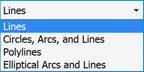
Result of Recognition
|
Type of vector objects to be recognized in raster images of sections: · Lines; · Lines, arcs and circles; · Polylines; · Elliptical arcs and lines. |
|
Save |
Closes dialog and saves changes. |
|
Help |
Call help. |