Information
In the program, you can obtain information about the selected point cloud or about a specific cloud point using the appropriate commands. Some information is displayed in the Properties bar.
 Ribbon: Point Clouds > Information >
  Compare
 Menu: Point Clouds > Information >
  Comparison
 Toolbar: Calculations and Information 3DScan >
  Comparison
 Command line: PC_COMPARE
The command allows you to visually evaluate:
· degree of coincidence of two point clouds with each other;
· degree of coincidence of the point cloud with its model, represented by vector objects. For example:
· Between the earth's surface cloud and the TIN built on its basis by the Create TIN command.
· Between the building cloud and the mesh based on it (Create 3D-mesh command).
· Between 3D vector objects obtained as a result of pipeline routing or the Creating Objects by Features command, and the pipeline cloud.
· Between the construction cloud and the IFC objects representing it.
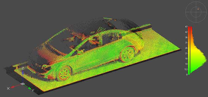
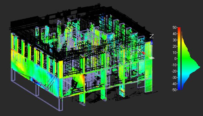
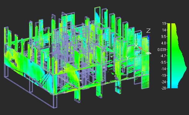
At the end of the work, the command repaints the point cloud in a spectrum of colors from blue to red, where each color indicates the degree of deviation from coincidence with the comparison object: matching points are colored green, points extending beyond the surface of the comparison object are colored from light to dark blue, points falling inside the object – from yellow to red, points that do not fall within the vicinity of the established deviation error at all – black.
After running the command, you will be prompted to:
1. Select reference objects (reference point cloud or vector objects). When you have completed your selection, press Enter.
2. Select a point cloud to compare with the reference. When you have completed your selection, press Enter.
3. Configure command options, if necessary.
The command options are set in the Properties bar.
Options:
|
Radius |
The distance within which the geometry is considered for comparison. If all points of the geometry with which we are comparing lie at a distance greater than the radius, then the deviation is considered infinite. Such points are drawn in black. If there are points in the compared geometry that lie at a distance less than the radius, the minimum distance is taken as the deviation. |
|
Discretization (0-auto) |
Technical parameter. Used to determine the number of splits of space into zones, within each of which points will be compared. The number of splits is calculated as 2 to the power of the value of this parameter. The parameter affects only the speed of the command, but does not affect the quality of the result obtained. By default, the mode of automatic determination of the sampling value is enabled (parameter value = 0). Automatic detection may not always be optimal. It makes sense to change the parameter if the command is running for too long. |
|
Use GPU |
Use of hardware capabilities that support DirectX 11, if available. It is not recommended to disable this option. |
|
Display legend |
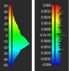
Enables a widget that displays the results of the command’s work in the form of a deviation distribution chart in the right side of the viewport. You can also disable the widget using the and enable – by
A similar diagram of deviations distribution can be viewed in the View Mode dialog for the Deviation value coloring type. |
|
Compute directions |
The Compare Point Cloud command calculates and displays the amount of deviation at each cloud point. The Compute directions option allows you to calculate and save deviation directions (deviation vectors) in the cloud. No custom attribute will be created to store deviation directions in the cloud. The directions of deviations will be recorded in the Normal attribute. If such an attribute is already present in the cloud, this will result in the loss of cloud normal information and a warning message will be displayed. |
Upon completion of the command, the Deviation attribute will be created in the cloud, and the Deviation coloring type will appear in the View Mode dialog (NPC_VIEWMODE command).
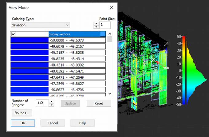
The Bounds button displays a histogram of deviations with the ability to cut off boundary values.
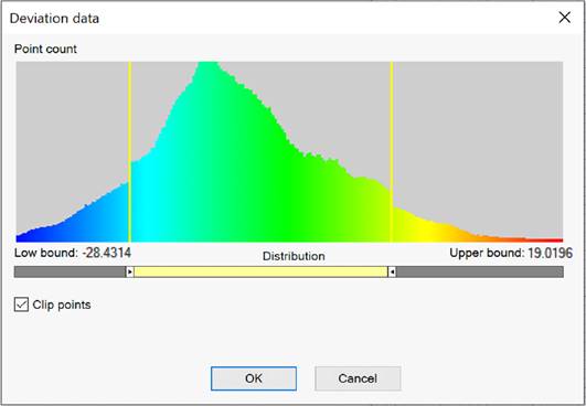
To disable the display on the screen of cloud points with deviations exceeding the acceptable range, you should adjust the range boundaries using the sliders and check the Clip points box. When the box is checked, points that do not fall within the set deviation error (black) will be cut off in any case, regardless of the position of the cut-off boundaries.
If the Compute directions option was selected in the Compare Point Cloud command, then in the View Mode dialog box for the Deviation coloring type will additionally have a Display vectors checkbox. The Normal coloring type will also appear.
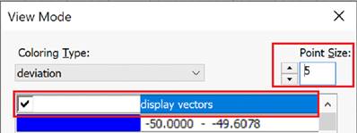
To display the directions of deviations on the screen, check the Display vectors box. The size of vectors on the screen depends on the size of the cloud point. Direction vectors are only displayed when using DirectX as a hardware graphics accelerator.
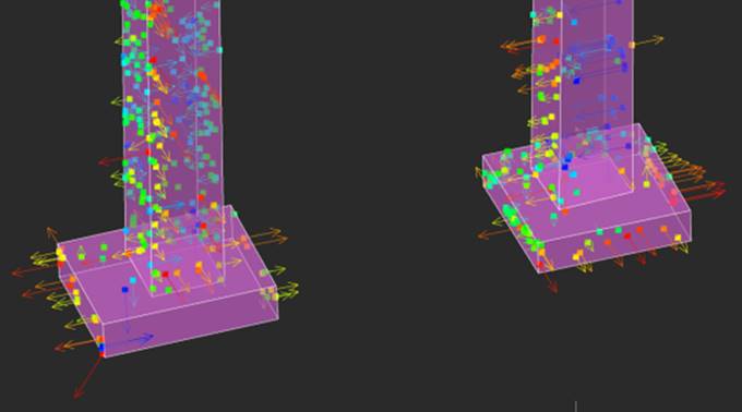
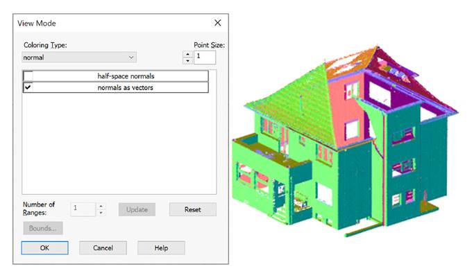
Since deviation directions are saved in the Normal attribute, deviation vectors can also be displayed using the Normal coloring type by checking the Normals as vectors box. However, the points color in this case will correspond not to the deviation value, but to the deviation direction, which is already clear when looking at the deviation vector.
In addition to coloring the cloud by deviation, you can recolor the cloud by deviation with the Recolor cloud by Deviations command, replacing the scan color with the deviation colors. Cloud recolor commands do not simply display clouds on the screen in accordance with one or another criterion/attribute, but change the values of the Scan Color attribute.


 De
De  Es
Es  Fr
Fr  Pt
Pt 


