De
De  Es
Es  Fr
Fr  Pt
Pt 

Pipe and Plane Tracing
 Ribbon: 3DScan – Features >
  Tracing Pipes and Planes
Menu: 3DScan – Features >  Tracing Pipes and Planes
Toolbar: Features 3DScan > Tracing Pipes and Planes
 Command line: PC_TRACE_POINTCLOUD
Interactive recognition and vectorization of pipes in the point cloud, taking into account the specified tracing parameters. The command does not require prior features recognition.
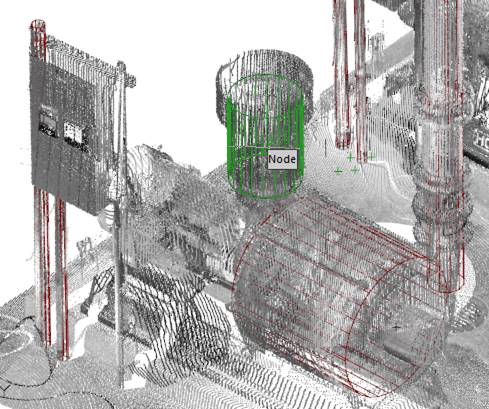
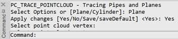
After running the command, select the type of tracing: plane or cylinder.
Select Options or [Plane/Cylinder]:
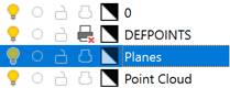
If the Plane tracing type is selected, a new layer will be created – Planes
Then, configure its parameters in the Properties bar.
Options:
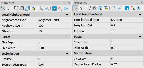
Local neighborhood
Normal determination parameters:
|
Neighborhood Type |
The way of specifying a sample to determine the normal at a point: · a sample made up of a certain number of nearest points, · or a sample composed of points that are within a given distance. |
|
Neighbors Count |
To calculate the normal at some point, the nearest points in the specified number are used. Typical value is 50-150. The larger the parameter value, the more accurate the position of the normals is calculated, but the longer the calculation time. It is recommended to increase the value when pipes are noisy or when there is a high density of points on the pipe surface. |
|
Neighbors Dist |
To calculate the normal at a point, points within the specified radius are used. |
|
Filtration |
The number of neighbors used to filter outliers in the vicinity of the point. |
Section
Parameters that determine the section size used for tracing:
|
Typical Density |
The estimated density of the point cloud surfaces. Specifies the number of cloud points per drawing unit. The parameter is used when tracing surfaces. The initial value is calculated automatically based on the cloud parameters. When setting manually, you can focus on the initial density value of 1-2 points per cm. A large density value can slow down the tracing process. To increase the size of recognized areas, decrease the value. If the values are too large or small, the planes will not be recognized. |
|
Slice Depth |
Slice radius in the units of the drawing. The maximum length and maximum diameter of the recognized pipe section depend on it (for example, 1m). |
|
Slice Width |
Section thickness in the units of the drawing, on average 1mm. It can be more or less depending on the quality of the scan (calculated automatically). |
Vectorization
Recognition parameters:
|
Accuracy |
A value between 0 and 10. It is recommended to set higher for good quality scans (e.g., handheld photogrammetric scanner) and lower for low quality scans (e.g., air scan). If the pipe is not detected, try to lower the value, if there are significant distortions – increase it. |
|
Segmentation Epsilon |
Segmentation radius in drawing units (calculated automatically). |
To start tracing, answer Yes to the request Apply changes [Yes/No/Save/saveDefault]. Press ESC to finish the command.
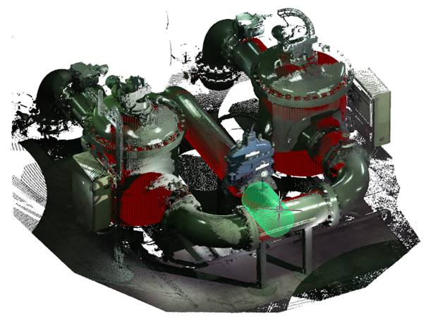
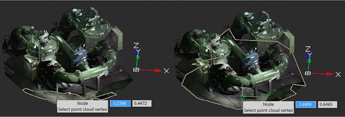
Tracing planes
Planes are traced by specifying points on the assumed cloud plane. As the cursor moves across the cloud, the trace command dynamically tries to recognize a plane in the neighborhood of the current cursor location and draw its contour on the screen. If the position and shape of the recognized area suits the user, click the left mouse button to create a contour in the form of a closed polyline at this location. Otherwise, continue to move the cursor around the cloud to display the best option.
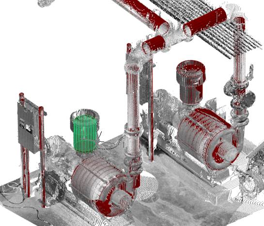
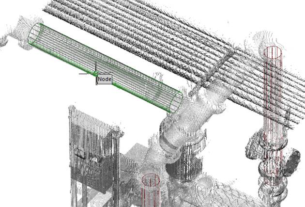
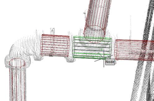
Tracing pipes
As you move the cursor over the cloud, the tracing command dynamically tries to recognize the pipe segment under the cursor and draw it on the screen. If the position and size of the recognized segment is as expected, click the left mouse button to create an object in this place. If not, continue to move the cursor along the pipe to display the best option.
During tracing, you can rotate and scale the workspace for better viewing, disable - enable modes and snaps to point clouds, use transparent commands.