Layer-by-Layer Vectorization
 Ribbon: 3DScan – Features >
  Layer-by-layer Vectorization
 Menu: 3DScan – Vectorization >
  Layer-by-Layer Vectorization
 Toolbar: Features 3DScan >
  Layer-by-layer Vectorization
 Command line: PC_WIRE_SKELETON_FROM_CLOUD
|
|
Note |
|
A drawing should contain at least onr point cloud for this command to run. |
This command vectorizes point cloud layer by layer. Set options in the Vectorization Settings dialog for this command.

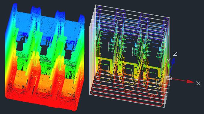
Layer-by-layer vectorization creates:
· Point cloud sections;
· Raster images of sections;
· Vector objects – lines, circles, arcs – that represents the shape of point cloud in a cut plane;
Sections will be created in the UCS plane (in Z axis direction) or in the current view plane (in view direction).
The command options are set in the Properties bar.
Options:
|
New UCS |
Specify coordinate system in command line to create sections: View or UCS. If the View option was chosen, then sections will be created one by one, starting from the current view plane, until the last point of the cloud. Otherwise, if the UCS was chosen, then sections will be created one by one, starting from XY plane of UCS in Z axis direction, until the last point of the cloud; |
|
Result type |
Objects to be created as a result of the command work. · Only_vectors – add only vector primitives (polylines, lines, arcs, circles) describing the section. The type of primitives that will be created is determined by the Result type option in the Vectorization Settings dialog; · Raster – add vector objects and raster images of sections; · Raster and clip – add point cloud sections, raster images and vector objects.
|
|
Step calculation method |
Methods for dividing the point cloud into sections: · By Steps Count · By Step Size
|
|
Step Count |
Number of cloud sections. The parameter is available if the Step calculation method is By Steps Count |
|
Step Size |
Step size. The parameter is available if the Step Calculation Method is By Step Size. |
|
Initial height |
The level from which the layer-by-layer vectorization of a cloud begins. |
|
Slice width |
The width of the cloud cross-sections (layers) to be vectorized. Excessive section width can lead to noise and thickening of contours, to the appearance of unnecessary contours and distortion of the topology, as a result of excess cloud points getting into the section. Insufficient width makes the contours thin and discontinuous due to the lack of cloud points falling into the section. Enter the value of the section width (in drawing units) using the keyboard. You can also measure the width in the drawing using the |
|
Max Edge |
Maximum length of the raster line to be analyzed when recognizing vectors. Raster lines with a length greater than the maximum will not be vectorized. |
|
Accuracy: |
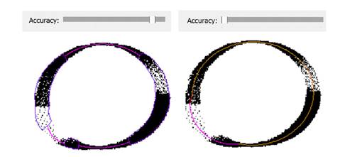
The accuracy with which vector objects should be recognized in cloud sections. The parameter is determined by the section quality, which depends on the cloud quality and the Slice Width. In some cases, what is required is not an increase, but a decrease in recognition accuracy. If the section quality turns out to be low, i.e. if the section is sparse and noisy with intermittent and unclear contours, then with high accuracy objects will not be recognized. In such cases, the accuracy should be reduced until the required objects and contours are recognized.
If the section quality is good, then with low accuracy, vector objects can be recognized in places where they are not present, or positioned incorrectly. In such cases, the recognition accuracy should be increased until the recognized objects are correctly positioned. |
|
Result type |
Type of vector objects that will be recognized on raster images of sections: · Lines; · Lines, arcs and circles; · Polylines; · Elliptical arcs and lines.
|
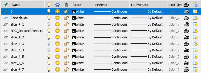
All objects are created at new layers slice_M_N, where: M – the amount of vectorizations in current session of program, N – sequence number of section. You can hide or show sections by turning on/off layers visibility in the Layers dialog.


 De
De  Es
Es  Fr
Fr  Pt
Pt 


 button in the