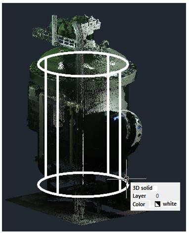
Fit Cylinder
 Ribbon: 3DScan – Features >
  Fit Cylinder
 Menu: 3DScan – Features >
  Fit Cylinder
 Toolbar: Features 3DScan >
  Fit Cylinder
 Command line: PC_FIT_CYLINDER
The command creates a cylinder (solid), fit into the cloud/section displayed in the current viewport.

The command analyzes a visible part of the cloud in the current viewport, therefore, before starting the command, use the crop and section commands to leave the part of cloud the cylinder should be fit into.
Command prompts:
|
Apply changes? <Yes> or [Yes/No/Save/saveDefault] <Yes>: |
Yes – the command will be performed taking into account changes in the settings made by the user in the current session of the command work. No – the command will be performed with the settings displayed immediately after running the command. Save – saving settings to a document. saveDefault – saving settings to the registry. |
The command options are set on the Properties bar.
Options:
|
Number of closest points |
Number of cloud points in the nearest area to calculate the normal to the surface. |
|
Number of iterations (axis) |
Number of iterations to determine the cylinder axis. The larger the value, the longer the calculation, but also the greater the probability of finding the correct direction. The parameter value should be more than 0. |
|
Number of iterations (point on axis and radius) |
Number of iterations to determine the point on the axis and radius. The larger the value, the longer the calculation, but also the greater the probability of finding the correct direction. The parameter value should be more than 0. |
|
Threshold distance (axis) |
The maximum value of deviation in location of the cloud points from the ideal one. I.e. spread of coordinates that can be neglected to assume that points belong to one line, surface, edge, etc. The threshold distance should be the greater, the less accurately the scan is performed, and the worse the object’s surfaces and edges are expressed. At the same time, with an excessive increase of the threshold distance the probability of an inaccurate location of the cylinder axis increases. |
|
Threshold distance (point on axis and radius) |
The maximum value of deviation in location of the cloud points from the ideal one. I.e. spread of coordinates that can be neglected to assume that points belong to one line, surface, edge, etc. The threshold distance should be the greater, the less accurately the scan is performed, and the worse the object’s surfaces and edges are expressed. At the same time, with an excessive increase of the threshold distance the probability of an inaccurate location of the cylinder axis increases. |
|
Draw axis |
Specify whether to create a line that displays the cylinder’s centerline in this and subsequent sessions of the command work. |
|
Draw solid |
Specify whether to create the cylinder solid in this or subsequent sessions of the command work. |
|
Draw diameter |
Specify whether the cylinder diameter should be created in this and subsequent sessions of the command. |


 De
De  Es
Es  Fr
Fr  Pt
Pt 
