Edit Features
 Ribbon: 3DScan > Features >
  Edit Features
 Menu: 3DScan > Features >
  Edit Features
 Toolbar: Features 3DScan>
  Edit Features
 Command line: PC_EDIT_FEATURES
The Edit Features toolbar displays a structured tree of geometric features of the point clouds of the current document. The toolbar allows you to hide and select features, edit their geometry using grips or changing the exact values of their parameters.
The Edit Features has a built-in toolbar, which is located under the window title.

 - Select features.
 - Refresh.
 - Move neighbors.
 - Delete feature.
 - Merge coaxial pipes.
 - Unisolate all features.
 - Isolate all features.
 - Show all features.
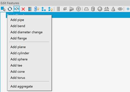
 - Creating new features.
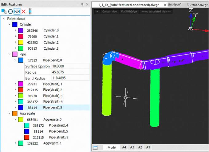
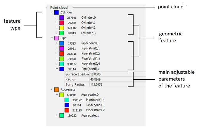
The toolbar displays point clouds in the document, the types of features recognized in them, a list of geometric features of each type.
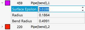
It is convenient to change the adjustable parameters using the up/down arrows. The parameters change depending on the tolerance accuracy: if the initial values are < 1, to tenths - by 0.1, to hundredths - by 0.01.
Selecting and displaying features
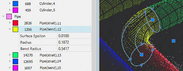
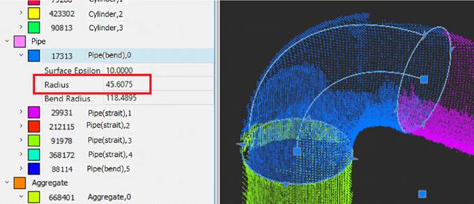
When you select a feature in the editor tree, it is automatically selected in the cloud in the drawing: it displays a frame indicating overall dimensions and functional grips. The selected feature allows you to edit its geometric parameters using grips. You can view and edit the exact values of the geometric feature parameters by expanding their list in the feature editor tree.
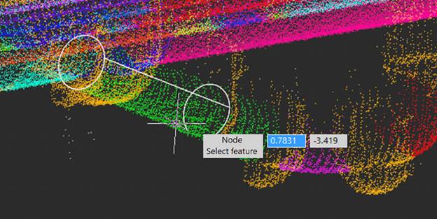
To select a feature by specifying it in the drawing, use the  Select Feature command on the Edit Feature toolbar. The command allows you to specify a feature in a cloud in a drawing, and then finds and displays that feature in the Feature Editor. While specifying a feature, hovering over an area of the cloud containing the feature displays its geometric contour.
Context menu of the toolbar element
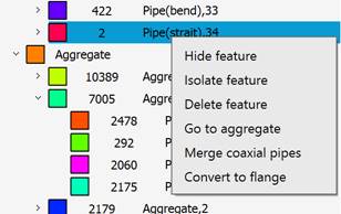
When you right-click on a tree element, a context menu opens with actions available for that element. Unavailable actions are displayed in muted color.
|
Creatimg new features |
|
|
Isolate feature |
Starts the isolation command and isolates the given feature. |
|
Unisolate all features |
Cancels the isolation of all forms. |
|
Delete feature |
Deletes a feature. The points lose their belonging to the feature and become part of the points with unrecognized geometry (gray color when coloring the cloud by Feature or Feature Type). This command can also be launched using the |
|
Go to aggregate |
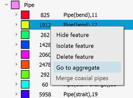
The action is available for aggregate forms – pipe elements. The command expands and displays in the tree the pipe line to which this element belongs.
|
|
Merge coaxial pipes |
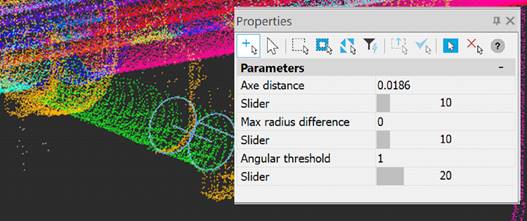
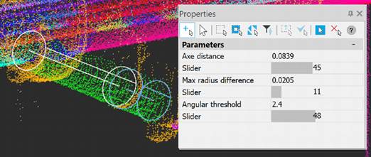
Runs the command to merge coaxial pipes. This command can also be launched by the In the Properties bar, increase the limit values at which independent parts of the pipe merge together.
|
|
|
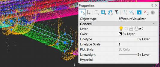
· Axe district – the maximum possible distance between the axes of two parts of pipes, at which they are still considered a single pipe; · Max radius difference – the maximum possible difference between the radii of two parts of pipes, at which they are still considered a single pipe; · Angular threshold – the maximum possible angle between the axes of two parts of pipes at which they are still considered a single pipe. The values are increased by moving the sliders to the right. Once the limit value is sufficient for the merge, the drawing will show the outline of the remaining parts of the pipe.
|
|
|
Upon completion of the command’s work, the pipe will become one. In this example, it was necessary to increase the maximum permissible gap between the axes of the pipes and the maximum permissible angle between parts of one pipe.
|
|
Convert to Flange |
Converts a cylinder or straight pipe into a flange. When converting a cylinder, it does not change (only after converting to a pipe it can be changed to a flange). |
Aggregate features
Features recognized as individual pipeline elements (pipes, diameter changes, bends, flanges, tees, etc.) are listed in the Pipe section.
The same elements are displayed in the Aggregate section, grouped by pipe lines.
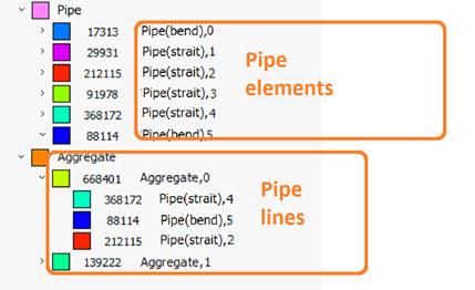
Double-clicking an element in the Aggregate section brings focus to the feature in the Pipe section, automatically displaying it in the drawing.
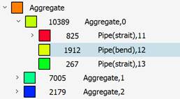
And vice versa. To find out which aggregate a particular pipeline element belongs to, open the context menu for the feature in the Pipe section and select Go to aggregate item. The command will expand and display in the tree the aggregate to which this element belongs.
Editing features
Each geometric feature type has its own editable parameters and functional grips.
|
Plane |
Displays the feature outline as a planar polyline with functional grips at its vertices. Using the dynamic menu that appears when you hover the cursor over the grip, you can add, delete vertices, delete a chain of vertices, add and delete additional external and internal contours. In addition, the flat feature displays an icon in the form of coordinate axes with their own grips that allow you to adjust the tilt of the plane. The following parameters are available for editing: Surface Epsilon. |
|
Edge |
Displays grips at both ends of the line. The following parameters are available for editing: Surface Epsilon. |
|
Node |
Has no grips. The following parameters are available for editing: Surface Epsilon. |
|
Cylinder |
Grips at both ends of the axis and radius handles are displayed. The following parameters are available for editing: Surface tolerance, Radius, Length. |
|
Pipe (Strait) |
The Pipe feature differs from the Cylinder in that it is included in the pipeline. Grips at both ends of the axis and radius grips are displayed. The following parameters are available for editing: Surface Epsilon, Radius, Length. |
|
Pipe (Diam change) |
Grips on both ends of the axis and grips on both radii are displayed. The following parameters are available for editing: Surface Epsilon, Radius 1, Radius 2, Length. |
|
Pipe (bend) |
Grips at both ends of the axis, the radius grips, and the center grip of the bend radius are displayed. The following parameters are available for editing: Surface Epsilon, Radius, Bend Radius. |
|
Pipe (flange) |
Grips at both ends of the axis and a radius grip are displayed. The following parameters are available for editing: Surface tolerance, Radius, Length. |
|
Pipe (tee) |
The connection point grip is displayed. The following parameters are available for editing: Surface Epsilon. |
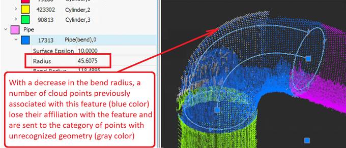
When editing the feature geometry, not only its parameters change, but also the membership of a subset of cloud points to this feature. Cloud points that no longer fall within the spatial area of the feature lose their belonging to the feature and pass into the category of points without belonging to the feature. This is clearly visible if the point cloud has Feature coloring type. In this case, immediately after changing the feature parameters on the EditFeature toolbar or using grips, the points that have lost their belonging to the feature are colored gray in the drawing field. And vice versa, points that enter the spatial area of a feature are immediately painted in the color of this feature.
Editing flat features
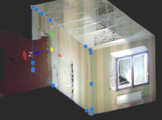
Such geometric features as Plane allow you to edit their vertices and contours using a dynamic menu that appears when you hover over the feature’s grip. You can add and delete vertices, add and delete internal or external contours, and delete a chain of vertices.
To delete multiple vertices, move the cursor over the grip of the geometric feature from which you want to start deleting. In the dynamic menu that appears, select Delete chain of nodes. When prompted in the command line, Specify the second vertex in the chain, click the last grip corresponding to the last vertex in the chain.
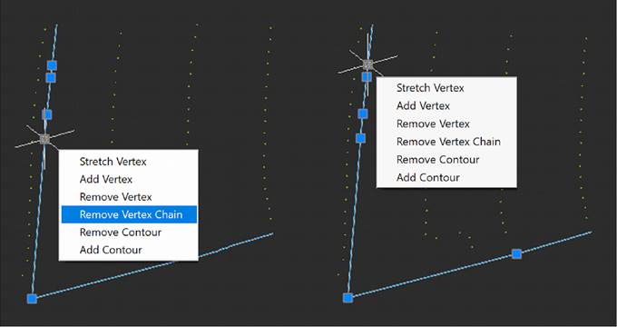
The chain of nodes from the first to the second vertex inclusive will be deleted.
To add a contour, hover the cursor over the grip of geometric shape. In the dynamic menu that appears, select Add contour or Add rectangular contour. In response to the prompt in the command line, specify the vertex points. Depending on your selection, a triangular or rectangular contour will be added.
Options for working with nodes:
Nodes in contours can be highlighted with a frame.
Selecting a chain of nodes: <Shift>+Click – the first node of the chain of nodes; <Shift>+Click – the last node in the chain of nodes
<Shift>+<Ctrl>+Click – switching node selection – from unselected to selected and vice versa
<Del> - deleting selected nodes, if no node is selected – the entire feature is deleted
<Esc> - reset node selection.
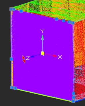
You can edit the position and orientation of the plane normal. When you select a flat feature, the coordinate system axes icon appears, where the normal of the plane is designated as the Z axis. Rotation of the normal (as well as the entire flat feature) is carried out using a grip with red arrows relative to the center of the coordinate axes, which in turn can be moved along the plane of the feature (yellow grip).
Undo and redo actions
To cancel or repeat operations with features, use the standard undo/redo commands (Undo/Redo).


 De
De  Es
Es  Fr
Fr  Pt
Pt 

 button in the feature editing toolbar.
 button on the feature editing toolbar. Before running the command, select a feature (pipe) that should be combined with the rest of parts. The outline of this pipe will appear in the cloud.