-
-
-
-
-
-
-
-
-
-
-
-
-
-
-
-
-
-
-
-
-
Creating a Pipeline Route
Creating a Pipeline Route
 Ribbon: 3DScan – Features >
  Creating a Pipeline Route
 Menu: 3DScan – Features >
  Creating a Pipeline Route
 Toolbar: Features 3DScan>
  Creating a Pipeline Route
 Command line: PC_AXE_TRACE
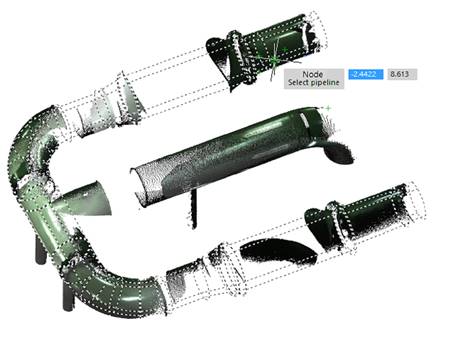
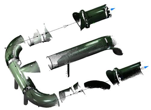
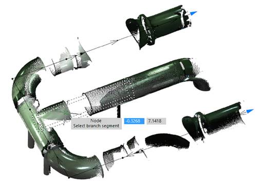
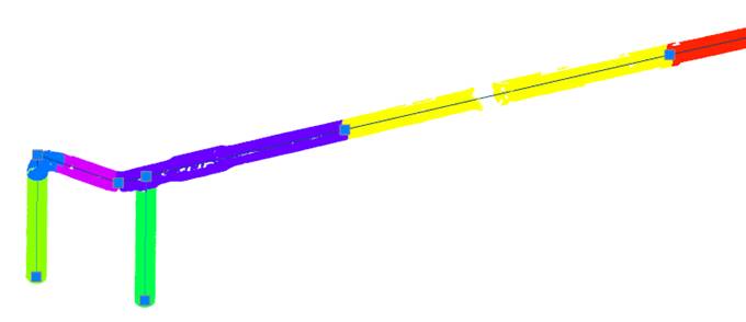
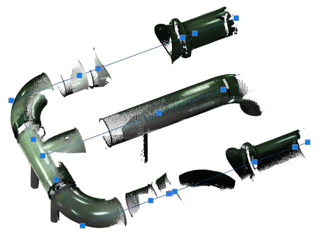
Visualization and coordination of the axes of pipeline segments (recognized or routed pipes) with the construction of a single route (center line) in the form of a 3D polyline. To build a route, it is enough to specify only the linear pipeline segments – turning points are determined and calculated automatically.
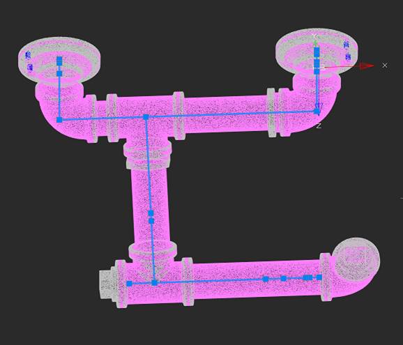
The Creating a Pipeline Route command works both on features recognized in the cloud by the Searching for Pipes in the Point Cloud command, and on objects resulting from pipe tracing.
Command prompts:
|
Select pipe segment or [Done/ Pipeline]: |
Specify the first straight pipe segment. The segment can be a feature recognized in the cloud by the Searching for Pipes in the Point Cloud command, or a 3D Solid object resulting from pipe tracing. Done – completes the creation of the pipeline route. Pipeline – allows you to specify the entire pipeline at once, instead of sequentially specifying individual segments.
Next, you can continue to specify the added segments or branches. |
|
Select pipe segment or [Done/Undo/ Reverse/ Branch]: |
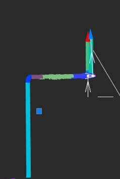
Indicate straight pipeline segments sequentially. The selected segments (recognized features or cylindrical 3D Solid) can belong to different routes and even different point clouds. The command receives data on the axes of these segments and adjusts them. Turning points are calculated automatically. The centerline is gradually created as a 3D polyline.
The end points of the route can be moved using grips strictly along the axis. Selecting the triangular axis extension grip rotates the view so that the route axis is aligned with the OY axis. When you release the grip, the view is restored.
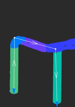
Undo – cancels the creation of the last route segment. Done – completes the creation of the pipeline route. Reverse – changes the direction of the route creation. You can select pipeline segments both from first to last and from last to first; only the order of the vertices in the constructed polyline depends on this. When rotating, the order of vertices changes, and the route will continue to be created from the other end. The direction of creating the route is indicated by arrows. |
|
|
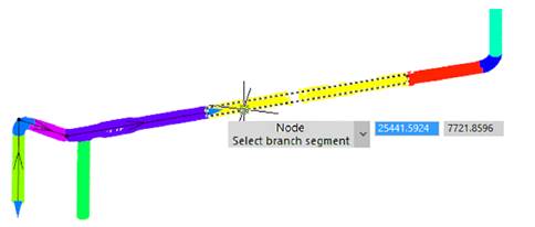
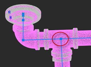
Branch – allows you to specify a pipeline branch to create a branch route. Simply specify a branch pipeline segment; a branch route will be created automatically at the appropriate location.
|
As a result of the command's work, a 3D polyline is created with nodes at turning points.


 De
De  Es
Es  Fr
Fr  Pt
Pt 

