Creating 3D-Mesh
 Ribbon: 3DScan – Meshes >
  Creating of 3D-mesh
 Menu: 3DScan – Meshes >
  Creating 3D-mesh
 Toolbar: Meshes 3DScan >
  Creating 3D-mesh
 Command line: PC_3D_RECONSTRUCT
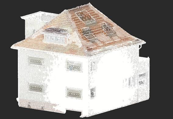
The command performs 3D-triangulation of point clouds of 3D objects with creating a mesh. It can be used for triangulation of buildings and other surface objects.

Point cloud

Triangulation mesh created by the Creating 3D-mesh command based on the point cloud
The command options are set in the Properties bar.
Options:
|
Reconstruction Depth |
Depth of triangulation performed. The higher is the value, the higher is the mesh level of detail. A typical value for this parameter is within the range from 6 to 10. Setting values higher than 10 (for example, 12) may require a very large amount of RAM (dozens of gigabyte). |
|
Trim Type |
The principle of trimming the edges of triangulation mesh. Each method displays its own adjustable parameters. · None – without trimming. · Bounding box – trimming mesh by the bounding box (particularly, parallelepiped) of Point cloud object type. The point cloud bounding box can be viewed by switching it on with Display cloud boundary command. · Depth – trimming by points density. Where there are few points, a mesh will not be created. The most universal trimming method. · Distance – trimming by a specified distance. Identical to trimming by Cropping the mesh by cloud command. After trimming, the mesh edge will be located no farther from the cloud than the specified distance. |
|
Smooth Iterations |
Option for Depth type of trimming The number of repetitions of smoothing depth values. 0 – without smoothing |
|
Trim Value |
Option for Depth type of trimming. The threshold value of depth for trimming (by 1-2 units less than Reconstruction Depth). It can be fractional, for example 5.5. |
|
Island Area Ratio |
Option for Depth and Distance types of trimming. If the ratio of cut parts area to the area of entire mesh is less than the specified value, the parts will not be trimmed. It is useful for closing small “holes” that appear when trimming. The range of acceptable values is from 0.0 to 1.0. Typical value: 0.01 – 0.05. |
|
Polygon Mesh |
Creates a polygon mesh with polygonal faces instead of triangle ones (mostly quadrangular). At that, the type of mesh created as nanoCAD object does not change.
Polygonal mesh is supported by not all mesh modification operations. |
|
Generate per vertex color |
When the flag is checked, the command creates a texture in accordance with the cloud points color and overlays it to a triangulation mesh as a material. When unchecked, a mesh is created without texture. The texture can also be overlayed to a mesh or redefined later. To overlay the texture by a point cloud to already created mesh, use Texture Atlas Overlay command. |
|
Generate normals |
Calculates normals at the mesh vertices, which results in a smoother appearance of the mesh. |
|
B-spline degree |
Spline degree (1-4). |
|
Double precision |
Yes – double, No – floating. |
|
Boundary type |
Determination of boundary conditions when solving Poisson's equations. Determines the behavior of the resulting mesh at infinity. Values – Free/Dirichlet/Neumann. The default value is Neumann, suitable for most cases. |
|
Scale factor |
The floating point value specifies the relationship between the diameter of the cube used for reconstruction and the diameter of the bounding cube. The default value is 1.1. |
|
Display log |
Output a command execution report to the command line. |
|
CGSolver Accuracy |
The default is 0.001, it is not recommended to change. |
|
Samples Per Node |
This floating point value specifies the minimum number of sample points that must fall into an octree node, as the octree design adapts to sampling density. For samples without noise, small values in the range (1.0–5.0) can be used. For noisier samples, larger values in the range (15.0–20.0) may be required to provide smoother, lower-noise reconstruction. The default value is 1.5. |
|
Point Weight |
This floating point value determines the importance of interpolating point samples when formulating the screened Poisson equation. Results from the original (unscreened) Poisson reconstruction can be obtained by setting this value to 0. The default value for this parameter is 4. |
|
Conjugate Gradients Solver Depth |
This integer represents the depth to which the conjugate gradient solver will be used to solve the linear system. Beyond this depth, Gauss-Seidel relaxation will be used. The default value for this parameter is 0. |
|
GS iters |
GS Iterations – This integer value specifies the number of Gauss-Seidel relaxations to be performed at each level of the hierarchy. The default value for this parameter is 8. |
|
Linear fit |
Use linear interpolation when determining vertex positions. |


 De
De  Es
Es  Fr
Fr  Pt
Pt 


