Classify Ground
 Ribbon: 3DScan – Classification >
  Classify the Ground
 Menu: 3DScan – Classification >
  Ground
 Toolbar: Classification 3DScan >
  Classify the Ground
 Command line: PC_CLS_GROUND
The command determines points located on the ground (according to the set parameters) and changes their Class attribute to class of the current layer.
The command options are set in the Properties bar.
Options:
|
Source classes |
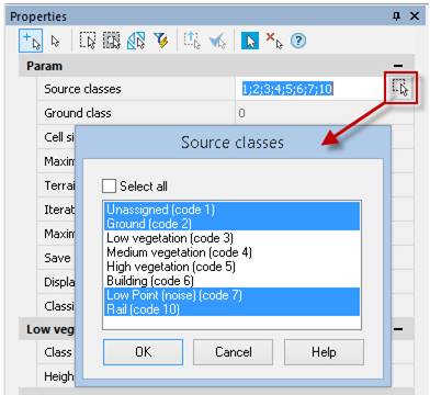
The classes that will be involved in the ground classification. Points of other classes are not subject to reclassification. The list opened by button
|
|
Ground class |
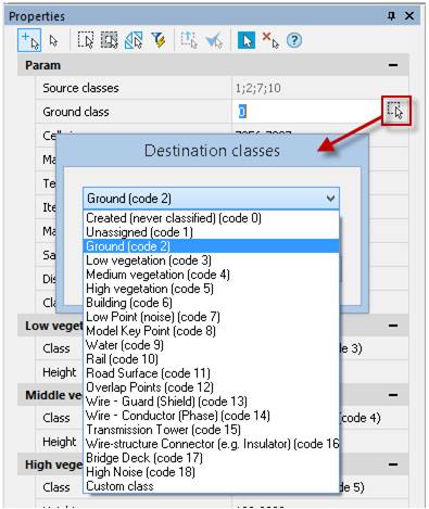
The destination class, which should be assigned to recognized points of the ground. The destination class should coincide with none of the source classes, otherwise the command will stop ahead of time with an error message in the command line.
|
|
Cell size |
Set the length of square cells which will split the area of point cloud (clouds). The smaller value is, the more precisely relief elements are displayed. Value should be more than 0. |
|
Maximum window size |
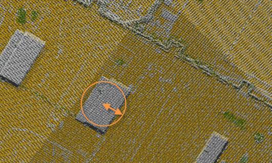
Size of artificial objects (buildings, cars, etc.) which doesn’t belong to ground. Objects are removed out of classification. Value should be larger than cell size. It is necessary to find the widest low object and measure a half of its shorter side, increasing the resulting value by 20 percent. For each cloud the parameter should be set manually in the units of drawing. Correctly measured parameter Maximum window size is always larger than the Cell size parameter.
|
|
Terrain angle, degrees |
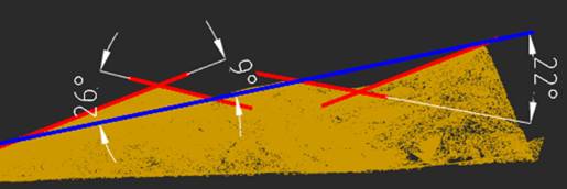
Maximum angle of slope in degrees relative to XY plane in WCS. It can be measured at some characteristic area. Points on surfaces that exceed this angle will not be classified as ground surface points. Should be in the range from 0 to 90.
|
|
Iteration angle, degrees to plane |
Maximum angle of deviation of local irregularities from the main direction of the ground surface.
|
|
Maximum distance |
Maximum distance above the ground surface, above which points will not participate in the classification process and, therefore, will not be classified as ground points. The distance is specified in the units of drawing. |
|
Method |
|
|
Border with |
|
|
Save ground model |
In addition to ground surface classification, the command allows you to automatically construct its triangulation model as a mesh object. Select Yes to keep generated TIN in the drawing after the end of the command. Unlike the TIN created with the Create TIN, command, this mesh is created with optimized edges. TIN can be optimized later with the Mesh Simplification command. |
|
Classify vegetation |
Classification of points (vegetation) by height above ground level. Set Yes for the Classify vegetation option, additional parameters will appear. These parameters are similar to the parameters of the Vegetation by Height command and described in the description of this command. |
|
Gap multiplier |
This value is multiplied by the Maximum distance parameter. If a point is at a distance from the triangle plane that is less than the calculated value, it subdivides the triangle it falls into. |
|
Min triangle side |
If a triangle has any side shorter than this value, it is no longer subdivided by ground points falling within it. |
|
Class |
Destination class for the low, medium or high vegetation. |
|
Height |
Height level for the low, medium or high vegetation in drawing units. |
Command prompts:
|
Apply changes? <Yes> or [Yes/No/Save/saveDefault] <Yes>: |
Yes – the command will be performed taking into account changes in the settings made by the user in the current session of the command work. No – the command will be performed with the settings displayed immediately after running the command. Save – saving settings to a document. saveDefault – saving settings to the registry. |


 De
De  Es
Es  Fr
Fr  Pt
Pt 

 , displays all classes of the current point cloud.


