-
-
-
-
-
-
-
-
-
-
-
-
-
-
Classification of Mesh
-
-
-
-
-
-
-
-
Classification of Mesh
 Ribbon: 3DScan – Meshes >
  Classification the Mesh
 Menu: 3DScan – Meshes >
  Classification the Mesh
 Toolbar: Meshes 3DScan >
  Classification the Mesh
 Command line: PC_MESH_CLS
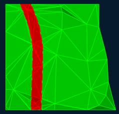
This command is used to divide the mesh into classes: for example, you can separate the road surfaces from lawn. For classification, it is necessary that closed polylines be created in the drawing, along which the mesh will be cut. After the mesh is classified, the resulting parts can be placed on layers to control their display (to adjust the visibility, color, transparency, etc.).
The command options are set in the Properties bar.
Options:
|
Project profile on |
Determines how the cutting polyline will be projected onto the mesh: · WCS - on the XY plane of the world coordinate system, · UCS - on the XY plane of the user coordinate system (if it exists), Viewport - on the plane of the viewport. |
|
Save result as |
The parameter affects the objects that will be created during execution of the command. Type of meshes to create: Subdmesh or Polyfacemesh. |
Command prompts:
|
Apply changes? <Yes> or [Yes/No/Save/saveDefault] <Yes>: |
Yes – the command will be performed taking into account changes in the settings made by the user in the current session of the command work. No – the command will be performed with the settings displayed immediately after running the command. Save – saving settings to a document. saveDefault – saving settings to the registry. |
|
Mesh before classification |
Mesh after classification |
|
|
|


 De
De  Es
Es  Fr
Fr  Pt
Pt 


