nanoCAD Platform
Editing
Download and open the Facade.dwg drawing file.
1. In the Properties, choose 3D Wireframe for the Visual Style (fig. 13):

Fig.13. Change the visual style
2. Turn off the visibility of the Shadow and Column layers. The visibility of layers can be changed by the bulb icon next to the layer name.
3. Select all objects with a Fence. Then use the Mirror command located on the ribbon: Draw – Modify – Mirror (fig. 14).

Fig. 14. The Mirror command
Use the red line as the axis of the mirror. Do not erase source objects. We do not mirror shadows and columns because they look different on the left and the right sides of the facade.
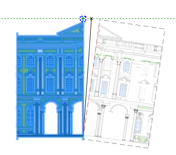
Fig.15. Mirroring
The result should be as shown in fig.16:

Fig. 16. The result of mirroring. General view of the facade
4. Turn on the visibility of the Columns layer and make it current. To make the layer current, just left-click on it.
5. Turn off the visibility of the Solids layer.
We use additional grey-green gradients for a more realistic view. We have created gradients on the right side of some columns to simulate shadows.
The result should be as shown in fig. 17:

Fig. 17. Intermediate result
6. Create shadows for the columns in any convenient way. Below is one of them.
Turn on the visibility of the Auxiliary layer. Select the following gradient by a left-click (fig. 18):

Fig.18. Gradient to copy
Run the Copy command. Specify the base point on the column, see the fig. 19:

Fig. 19. Base point for copy
Paste this gradient on the right side of the top columns (fig. 20):

Fig. 20. Copy gradients for the top columns
Repeat the actions for the bottom columns (fig. 21):

Fig.21. Copy gradients of the bottom columns
Turn off the visibility of the Auxiliary layer.
Keep three columns without gradient (fig. 22):

Fig. 22. Columns without gradient
7. Working with gradients.
Please note that the center of the building has incorrect gradients due to the Mirroring (fig. 23):

Fig. 23. Incorrect gradients
8. Edit these gradients.
Double click on one of them, then swap two colors in the Gradient tab of the Hatch dialog box (fig. 24):
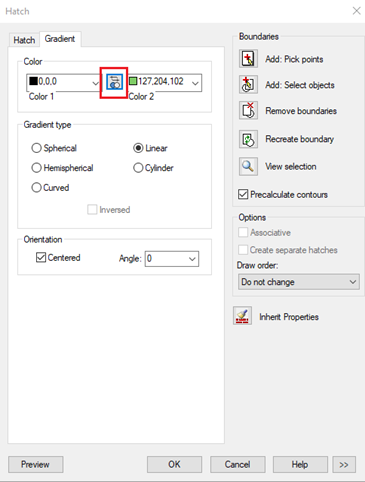
Fig. 24. Swap colors in the gradient
Do the same with the second incorrect gradient.
9. Add a new gradient to the building's top and bottom.
First, you set the Additional gradients layer current. Next, call the Gradient command on the Annotate tab (fig. 25):
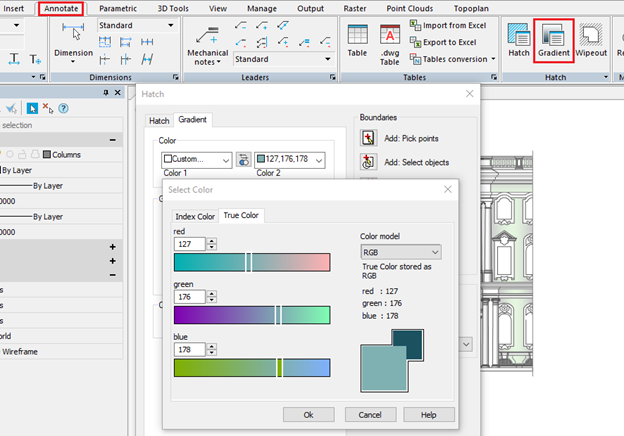
Fig. 25. Choose gradient colors.
Set the following values: Color 1 = 83, Color 2 = 127,176,178. Choose the Cylinder + Inversed gradient type.
Add two pick points (fig. 26):
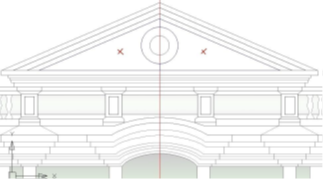
Fig. 26. Gradient pick points
To speed up the gradient outline, select as close as possible, but make sure that the borders fit the screen.
As a result, you get a bright, saturated color of the gradient. To make it the same as other gradients, select this gradient and set Transparency = 80 in the Properties (fig. 27)
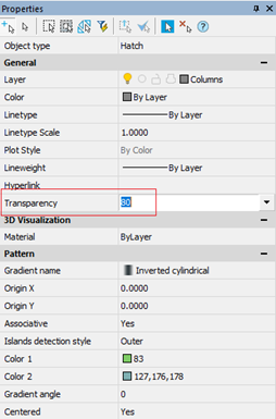
Fig. 27. Change transparency of the gradient
10. Set the correct gradient display.
- Set the Main layer current.
- Turn off the visibility of the Additional gradients layer, and select all objects with a Fence.
- In the Properties, choose Hatch in the Object type field (fig. 28):
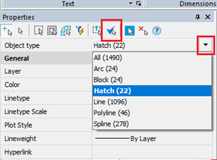
Fig. 28. Select only hatch
Move the selected hatches to the background: right-click on the workspace – Display order – Send to back
11. Turn off the visibility of the Columns layer.
12. Turn on the visibility of the Shadows layer and set it curren.
13. urn on the visibility of the Right shadows layer. We finished the rest of the shadows. The result should be as shown in fig. 29:
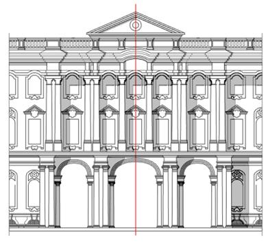
Fig. 29. The final display of shadows on facade
14. Complete the drawing.
Delete the middle red line. Turn on the visibility of the following layers:
- solids
- additional gradients
- columns
- final
15. The facade is finished. The final result should be as shown in fig. 30:
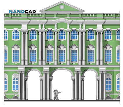
Fig.30. Final view of the Facade


 De
De  Es
Es  Fr
Fr  Pt
Pt 
