nanoCAD Platform
Design
In this part, we will add benchmarks and dimensions to the drawing.
Open the Faсade Desing.dwg file (fig.31):
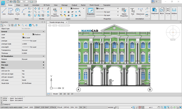
Fig. 31. The Faсade Design.dwg drawing file in nanoCAD
1. Make the Design layer current.
2. Add a dimension between axes: Annotate – Dimension – Aligned – enter dimension between two axes on the drawing (fig. 32):
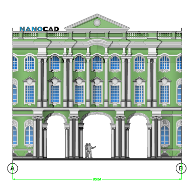
Fig. 32. Dimension
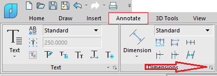
3. Set the dimension style. Click on the Design tab and open the Dimension Style dialog box (fig. 33):
Fig. 33. Run the Dimension Style Manager
Select the current dimension style and click Modify (fig. 34):
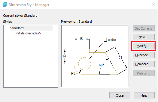
Fig. 34. Dimension Style Manager
In the Lines tab, configure the following settings:
- Color of Dimensions lines – white
- Color of Extension lines – white
In the Text tab set the text color as white (fig. 35):
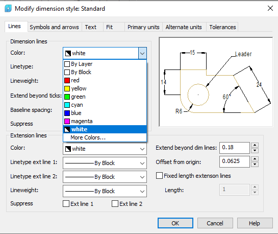
Fig. 35. Edit the dimension style
Click OK, then close the Dimension Style Manager.
4. Insert a block with a benchmark.
Run the Insert Block command in the Insert tab. Press the Browse button and select Bechmark.dwg file (fig.36):
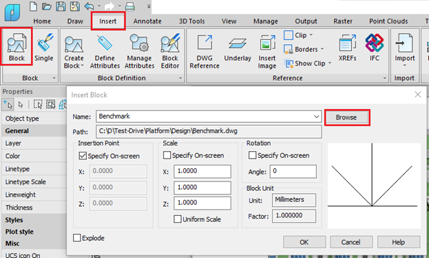
Fig. 36. Insert block from the file
Click OK. Insert the block three times and add attribute values as shown in fig. 37:
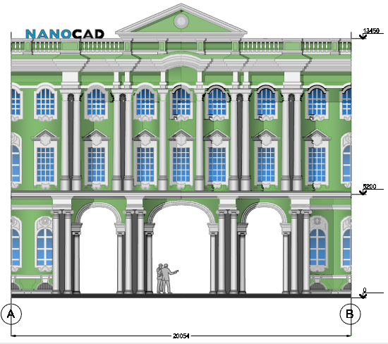
Fig. 37. Final drawing


 De
De  Es
Es  Fr
Fr  Pt
Pt 

