
 De
De  Es
Es  Fr
Fr  Pt
Pt 

Migrating to nanoCAD
When migrating to nanoCAD, the first thing you notice is a familiar ribbon-type interface, similar to AutoCAD. Despite the visual layout, we will see some similarities in features in the first section:
User Interface
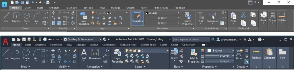
Fig. 1. Ribbon interfaces of nanoCAD and AutoCAD
Look at the user interface of nanoCAD through the eyes of an AutoCAD user. The first thing you see is the similar layout of command tabs and groups. For users who are more used to working with the classic interface, there is an option to switch to the classic interface in nanoCAD. Just click the top right button on the screen — Ribbon on/off Ribbon (see Fig. 1).
Command Line
The command line is a panel designed to input commands using the keyboard. It also displays nanoCAD tips, system messages and options available for the running commands (Fig. 2).
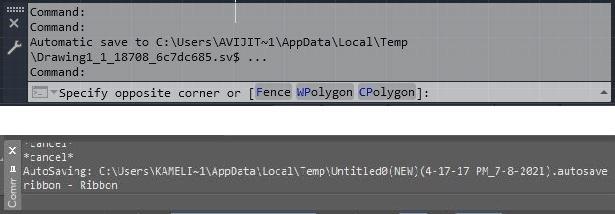
Fig. 2. Command lines in nanoCAD and AutoCAD
The command lines in nanoCAD and AutoCAD look identical. For a more convenient view of the command protocol (or so-called command history) you can open a text box (a copy of the command line) by pressing the F2 key.
You can see the list of all nanoCAD commands with their aliases by typing " ‘ " in the command line.
Status Bar
The status bar shows the cursor position in the coordinates and drawing tools. With the right click on the status bar you can open the contextual menu – Status Bar Configuration (Figure. 3), with a list of possible Status Bar elements. It allows you to fully customize the status bar by excluding/adding items through the context menu.
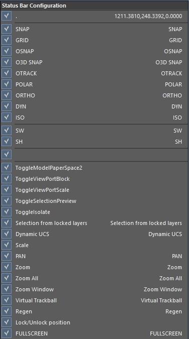
Fig. 3. Status bar context menu
Drawing Layouts’ Tabs
When a new drawing is opened, nanoCAD creates four sheets with the most popular document sizes: A4, A3, A2 and A1. You can adjust the number and location of the sheets when you start using the templates (see “DWT and DWS Standard Files”).To switch between the model space and the sheet, use the button located at the bottom left of the drawing layout tabs (See Fig. 4).
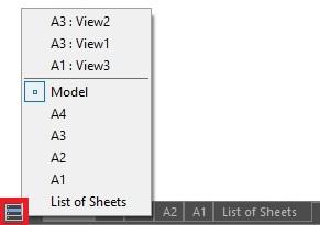
Fig. 4. Drawing Layout Tabs
Toolbars
Toolbars can be added to both the ribbon and the classic interfaces. You can call the window with a list of available toolbars (Fig.5) by entering the command "Toolbars" in the command line:
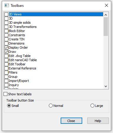
Fig. 5. Toolbars window
In the window, you can choose the toolbars you want to add to the interface, as well as the look of the toolbars and the size of the buttons. Any custom toolbars you create are also added to this list (see “Interface Settings”).
You will find a number of buttons on the toolbars to run specific commands. When you place the mouse over a button icon, a hint pops up with the command name (Fig. 6).
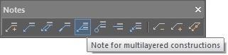
Fig. 6. Example of a toolbar
Interface settings
You can always customize the interface. Go to the settings and adjust the interface layout (ribbon/classic), visibility, order and location of the toolbars, as well as the look of the command line and the status line, which is everything around the interface.nanoCAD interface settings files are located at the directory:
%AppData%\Nanosoft\nanoCAD XX\Config
Unlike in AutoCAD where the settings files have an *.cuix extension, nanoCAD custom interface settings files have various extensions.*. cfg - classic interface: menus, panels, hot keys, state line, contextual menu
*. xml - ribbon interface
*. pgp - team aliases
*. cuix - additional app interface
Almost all the information about the interface is stored in the configuration files *.cfg.
To open the Customize user interface window run the INTERFACE command (Fig. 7).
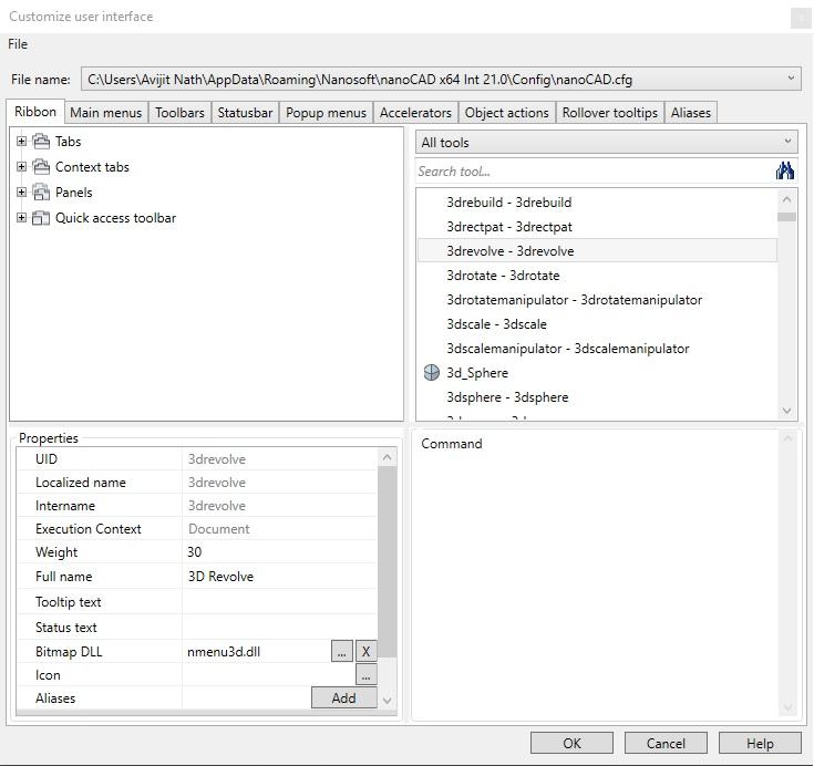
Fig. 7. Customize user interface settings
In the window, you will see the File tab that contains a list of operations with configuration files.
Customize window options
| File |
Configuration file management commands:
|
|
File name |
The field shows the path and name of the edited .cfg file. The current configuration file opens by default. |
The window contains 9 tabs arranged in accordance with the command layout on the interface. The full list of the selected tab’s elements is displayed in the upper left window of the Customize user window as a tree.
In the upper right section of the window, you will see all nanoCAD tools, commands and controls to create and edit interface objects, such as menus, toolbars, and status bar.
You can filter the list for a quicker tool search:
- Dropdown list — select a category to display its group of elements.
- Search tool — type the name to find a specific list of tools.
You will see the information about the item / action selected in the bottom right corner of the dialogue window.
In the Properties section (bottom left of the dialogue window) you can edit the properties of the selected items.
In nanoCAD, you can set command aliases (alternative names) in the interface settings (Aliases tab), unlike in AutoCAD. Several aliases can be assigned to the same command. Each specific alias can be assigned only to one command. All aliases are automatically written to the *.pgp file.
When you complete the interface configuration update the ribbon or restart nanoCAD, depending on the changes made. If you want to apply the changes to the classic interface elements, restart nanoCAD. To apply the changes to the ribbon elements, use the RELOADRIBBON command or Alt+R (no need to restart nanoCAD in this case).
Exporting and importing interface settings
A partial configuration file allows you to add all the necessary settings without making changes to the main nanoCAD.cfg interface file. For an X transfer of the user interface settings across multiple environments, we recommend creating them in a partial configuration file. In this case, you will just need to connect the user to the *.cfg files while migrating to a new version or another workstation. You can assign any name to the partial configuration file, but the main file will have a reserved name by default — "userdata.cfg". It means that the user settings files with this name will not be connected when upgrading to new versions.There are special commands in nanoCAD for a quick import / export of interface settings — UIIMPORT and UIEXPORT.
The UIEXPORT command creates a UIConfigs.zip archive that contains the following settings:
- New menus, toolbars, contextual menus
- Added commands in a menu and a toolbar
- New commands created by the user
- Edited composition and interface settings
- Actions over objects, hot key combinations, tooltips and synonyms
- Interface type (classic or ribbon interface)
- Visibility and location of toolbars (toolbar)
- Visibility, location, attachment and size of a toolbar
- Visibility, location and size of the command line
- The ribbon display
- Visibility of ribbon bookmarks
To transfer the interface settings to another workstation:
- Use the UIIMPORT command.
- Choose an archive with the right settings.
- Restart nanoCAD.
The file package includes a saveduistate.cfg file with the settings for the location, visibility, and size of the interface elements on the screen. You can also create this file with SAVEUISTATE.
To transfer only the saveduistate.cfg file to another workstation:
- Start saveuistate command.
- Choose where saveuistate.cfg is saved.
- Transfer to another computer and save saveuistate.cfg file in the folder:
%AppData%\Nanosoft\nanoCAD XX\Config
Option settings
Program parameters settings include information about template usage, graphic subsystem, interface themes, and everything related to displaying objects in the model (cursors, grips, crossing frames, etc.).You can find all nanoCAD settings on the same tab with the OPTIONS command. They form a tree of files for a quick search (Fig. 8):
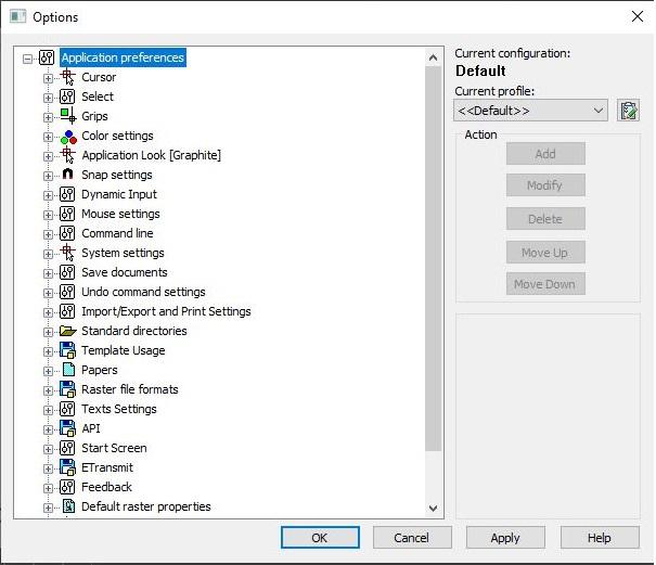
Fig. 8. Options window
The information about the option's settings is stored in the registry editor. All changes that are included in the option settings dialogue can be recorded in the profile (Default profile) with the *.wip extension. Then, this profile can be easily exported / imported from/to other workstations.
You can set the paths of standard folders in the Standard directories section of Option settings. Read about each Standard directory in more detail below.
Standard directories
The installation of nanoCAD includes a fairly large number of files (line types, fonts, hatchings, templates, print styles, etc.) that are placed in so-called standard folders. By default, all files are placed on C:\ drive in hidden folders: either in AppData, or in ProgramData.SHX files
Font and shape files (*.shx) are located at the following address:C:\ProgramData\Nanosoft\nanoCAD XX\SHX
The fonts are NOT stored in the *.dwg files.- Transfer *.shx files to the SHX folder or add a SHX file location to standard nanoCAD directories (see transfer of Standard directories).
- TTF fonts are automatically loaded into nanoCAD after installation.
The nanoCAD software has the font CS_Gost2304.shx used to create the Text style GOST 2.304 (Fig. 9):
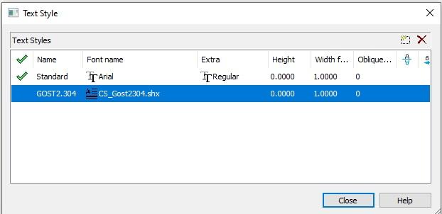
Fig. 9. Text style window
Hatch sample files and line types
The SHX folder also contains the files with lines types (*.lin) and hatching files (*.pat). We recommend adding custom line types to the end of the ncadiso.lin file for a smooth transfer to future versions of nanoCAD. You can open this file type with any text editor.Line types can be loaded into * dwg and * dwt files in the nanoCAD interface:
- Go to the Home tab — Annotation Group — open dropdown menu — select Line Types.
- In the Linetype Manager window select Load linetype (Fig. 10):
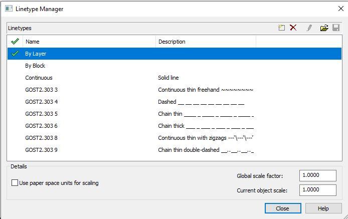
Fig. 10. Linetype manager window
The linetype file GOST 2.303–68.lin is installed automatically with nanoCAD. The linetypes from the file can be downloaded in the dwg files.
DWT and DST template files
*.dwt file format is called drawing templates. Templates contain presets with drawing parameters. The *.dwg files created with these templates will have the following preset parameters:- Units
- Drawing modes
- Layers and their properties
- Line types
- Dimensional style
- Text style
- Sheets with views and scales
- Print options
The templates are stored at the following location:
%AppData%\Nanosoft\nanoCAD XX\Templates
AutoCAD template files are located at the directory:C:\Users\username\AppData \Local\Autodesk\AutoCAD XX\R24.0\ enu\Template
Save a *.dwg file with specified parameters and styles in the *.dwt format to create a new template (Fig. 11):
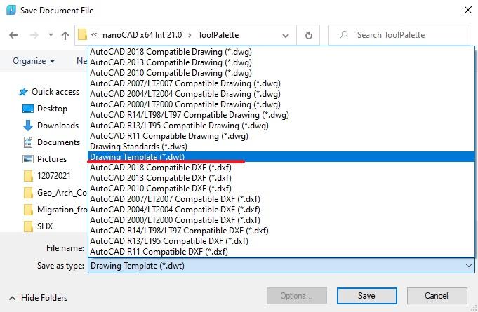
Fig. 11. Create a template in DWG format
If you want to use AutoCAD templates, we recommend moving all the necessary * dwt files to the standard nanoCAD Templates folder.
In the Options (OPTIONS command) choose a template usage (Fig. 12). This setting allows you to select desired templates from the standard Templates folder and display them as a list. When creating a new document, select a path for the template location, or use the default template (enter the default template file name).
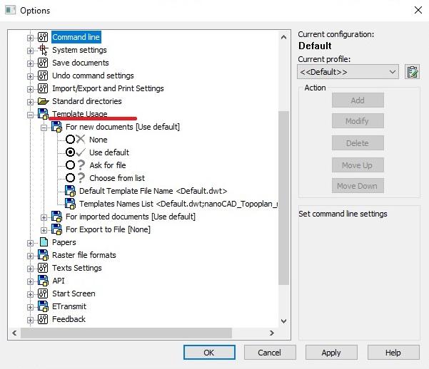
Fig. 12. Setting up a Template Usage
In addition to (*.dwt) templates, in the nanoCAD and AutoCAD Template folders, you can find template files of sheet sets (layouts) with *.dst extensions. The process of working with the nanoCAD sheet sets is the same as in AutoCAD.
DWS Standards Files
The files in *.dws format are called Drawing Standards.Standard files are not included in the nanoCAD. They are created by users based on project standards. To create a standard, you need to open a *.dwt template file with the specified parameters and styles, and then save as in the *.dws format (Fig. 13).
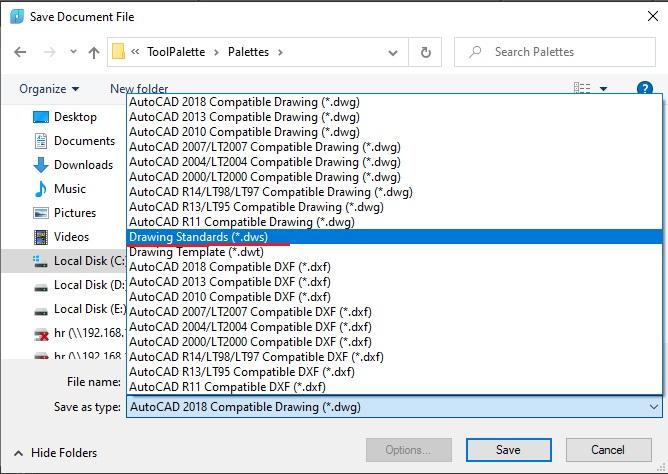
Fig. 13. Creating a standard based on DWT-template
To link a standard to new files based on the DWT template, do the following:
- Open the .dwt file and run the STANDARDS command
- In the opened Configure Standards window, click the "+" button (Fig. 14)
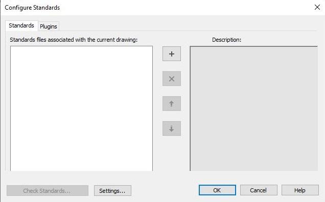
Fig. 14. The Configure Standards Window
Make sure that the path to the dws file location remains the same. In this case, you will not need to change the paths at a new system when linking a DWT template to a DWS standard. Just place the standards in a folder with the same name and the same path. No need to rebind the standard to the template.
Transfer of standard folders
You can transfer Standard files from AutoCAD to nanoCAD in two ways:- "Physical" — copy files from AutoCAD folders to nanoCAD folders with Ctrl+C and Ctrl+V
- "Software" — let’s see how it works on the example of SHX-fonts:
- Open the Options dialog box in nanoCAD.
- Expand Standard directories to subsections.
- Select the "SHX files location" and click Add on the right (Fig. 15).
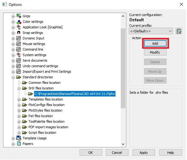
Fig. 15. Selecting Standard directories
- Click "Browse" (Fig. 16):
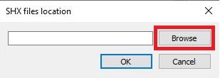
Fig. 16. Window to add a Standard directory
- Find the Fonts folder and click OK:
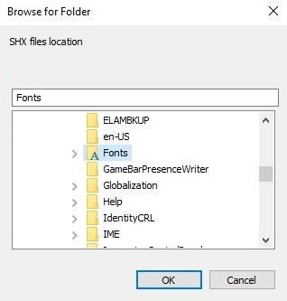
Fig. 17. Browse for Folder Window
Restart nanoCAD to see all the downloaded fonts in the SHX and the Fonts folders (Fig. 18):
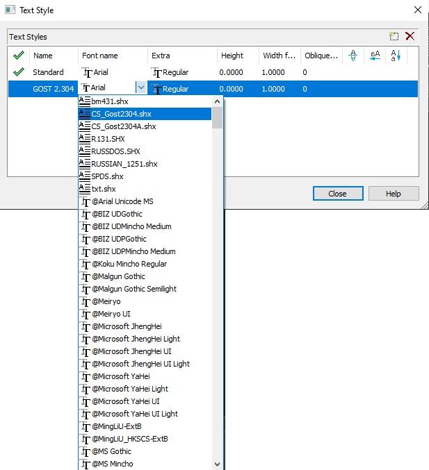
Fig. 18. List of fonts
In the Standard Directories of nanoCAD, you can not only add directories with existing files, but also change their locations.
Configuration files and print styles
Here is the standard location of the plot configuration files in nanoCAD:%AppData%\Nanosoft\nanoCAD XX\PlotConfigs
Plot configuration files store plotter settings. If you used your own plotter settings in AutoCAD, transfer them from the Plotters folder located at the directory:%AppData%\Autodesk\AutoCAD XX\R24.0\ enu\Plotters
Here is the location of named (*.stb) and color-dependent (*.ctb) nanoCAD plot styles:%AppData%\Nanosoft\nanoCAD XX\PlotStyles
AutoCAD printing styles are stored in the Plot Styles folder:%AppData%\Autodesk\AutoCAD XX\R24.0\ enu\Plotters\Plot Styles
Tool Palette files
Custom blocks, formats, line types, table libraries pre-configured for certain layers and many other files are stored on the Tool Palette.The Tool Palette is a tree of sets and groups that contain different tools. By default, the tools are arranged by groups of related commands.
To launch the Tool Palette, go to the Manage tab the Palettes group Tool Palette.
All the toolboxes and the NcTcCatalog.ntc catalog can be found on the Palette. They are stored in a folder at the following path:
%AppData%\Nanosoft\nanoCAD XX\ToolPalette
You can transfer custom tool sets from AutoCAD to nanoCAD in the following way:Open the existing AutoCAD Tool Palette.
- Right-click on an empty space on the AutoCAD Tool Palette — select "Customize Palettes..." on the context menu (Fig. 19):
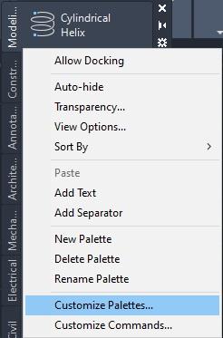
Fig. 19. Tool palette in AutoCAD
- In the Customize window, right click on the palette you need — Export... (Fig. 20):
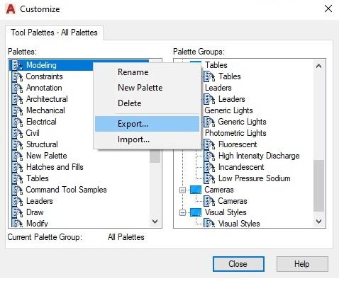
Fig. 20. AutoCAD Customize Palettes
- In nanoCAD, right-click on "Tool Palettes" - "Import palette..." (Fig. 21):
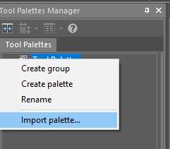
Fig. 21. Importing a Tool palette in nanoCAD
- Choose the *.xtp file.
%AppData%'Nanosoft'nanoCAD XX/ToolPalettefolder.
Setting up elements
The design parameters are set in the Design Setting window.Unlike in AutoCAD, nanoCAD design elements are customizable. You can change the Settings nanoCAD for enterprise standards. By default, all the design elements are configured in accordance with ISO.
To edit standard settings, open Design Settings - Main tab - Common settings
You can see the path to the current settings * .xml file in the window heading * (Fig. 22):
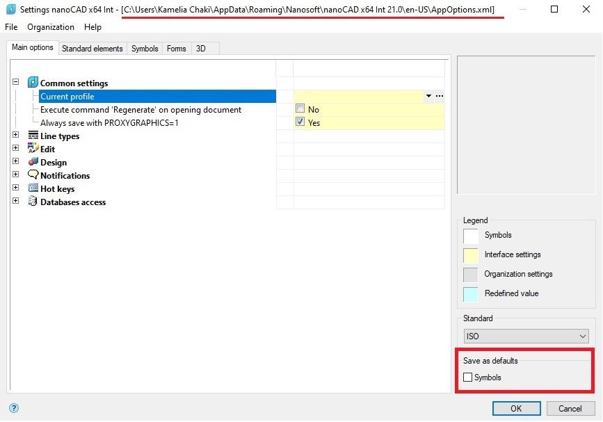
Fig. 22. Window for configuring nanoCAD elements
Check the box "Save as default" in the bottom right corner to save the settings between subsequent sessions of nanoCAD.
To transfer the design settings to other workstations, do the following:
- Open the "Settings nanoCAD x64 Int" dialog box, click "File" "Save settings as..." (Fig. 23).
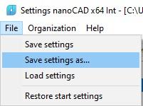
Fig. 23. Saving object settings
- Transfer the * .xml file to the en-US folder on another workstation at the directory:
%AppData%\Nanosoft\nanoCAD XX\ en-US
Here are the locations for Construction and Mechanica modules:
%AppData%\Nanosoft\nanoCAD XX\NanoSPDS\ en-US
%AppData%\Nanosoft\nanoCAD XX\NanoMechanical\ en-US
- Open the Design Settings window, click on the “File” "Load settings”, and select the file.
Database
The database (DB) in the nanoCAD platform contains table templates. In vertical applications, the element base is presented as an additional functional panel. It includes table and format templates, default assembly templates, groups and markers, as well as examples and other custom elements. It is possible to import and export folders with custom files in addition to standard elements.In nanoCAD, two DBMSs are supported: PostgreSQL and Microsoft SQL Server. Network PostgreSQL is deployed by default.
It is quite simple to change the database on an already installed nanoCAD, if needed. Just do the following:
- Start the params command.
- In the Main Settings tab, open the Databases access.
- Click on "..." at the right end of the Data Source.
- Specify the Server and Database for the network database in the data source or the path to the local database (Fig. 24).
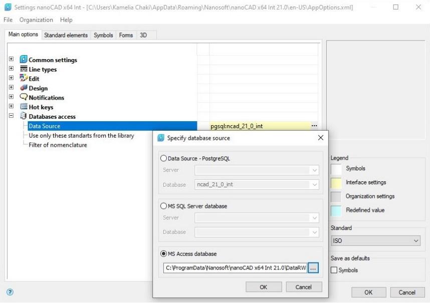
Fig. 24. Window for specifying a data source
In order to configure the installation packege for bulk installation of network MSSQL, use the Installation Guide.
In the Construction and Mechanica modules, you can add your own folders to the default folder. If you are using a network database, these folders can be easily transferred to other workstations, by selecting features in Configuration Utility for example, the "Publishing" feature.
To export the elements from the Construction and Mechanica modules, do the following:
- Start the functional panel "Library" (the Tabs command – Library)
- Right-click on the desired folder and select "Export object" from the drop-down menu (Fig. 25)
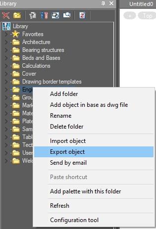
Fig. 25. Exporting the Library objects
3. Specify the path to save the folder.
4. * mcdi file is ready for import.
To import the library in the Construction and Mechanica modules, go through these steps:
- Open the Library panel (the tabs command - Library);
- Right-click on the top line of the "Library" and select "Import object" from the dropdown menu (Fig. 26):
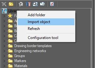
Fig. 26. Importing the Library objects
Choose the *.mcdi or *.mcd file. A folder with the file name should appear in the Library.