nanoCAD Mechanica Module
Shaft Editing
Open the Shaft end.dwg file.
Leave the default properties and close the dialog.
In the Shaft Segments section select the Shaft element (Fig. 15).
New sections of the shaft are automatically snapped to the model when you move the cursor over an existing section.
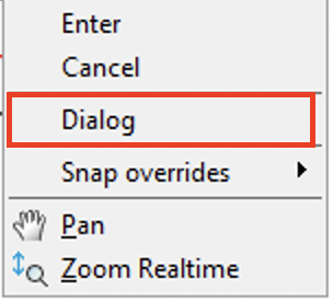
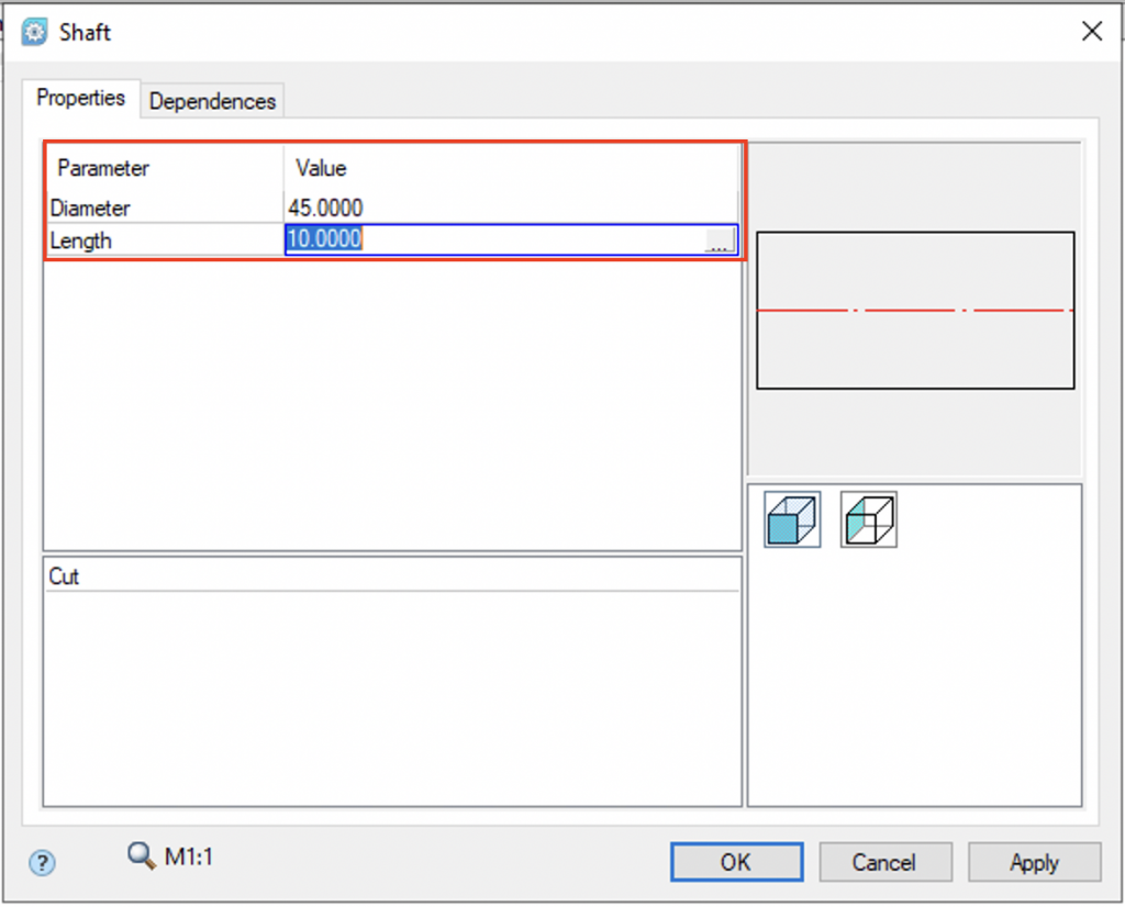
Right-click and select the Dialog command from the context menu to set the dimensions of the sections. In the dialog box, enter the required values, and click OK (Fig. 16).
Specify the end face of the section with a chamfer, leave the default values, and click OK (Fig. 18). Cancel the command by pressing Esc. Close the Shaft editing window. The result is shown in Fig. 19.
Save the file to the Exercises folder.
1. Start the shaft end editing with a double click on its contour.In the Properties tab of the dialog box that appeared, change the parameters provided by the relevant standard for the shaft end (Fig. 8). Click Apply to see the changes.

Fig. 8. Changing shaft end parameters
Leave the default properties and close the dialog.
2. Now, let’s edit the first section of the shaft.Double left-click on the axis (Fig. 9). In the Edit Shaft dialog box you will see the sequence for creating the shaft segments. When you select a segment, its geometry will be highlighted. Click the diameter field of the first shaft section and enter the value 45 on the keyboard (Fig. 10). Do not close the dialog.

Fig. 9. Resizing a shaft section interactively
3. Create a gear on the shaft.
3.1. Click MCS\Tooth-wheels button located in the bottom part of the window.

Fig. 10. The Edit shaft dialog
3.2. Select Spur pinion (Fig. 11) from the elements that appear.

Fig. 11. Spur pinion element
3.3. Pick a point to insert the gear. Move the cursor to the first section of the shaft.The area is highlighted in green to indicate that the pinion is automatically connected to the shaft (Fig. 12). The created object will be one-piece. Left-click to confirm the insertion point.

Fig. 12. Picking the insertion point for the pinion
3.4. You will see the gear parameters in the Spur gear dialog (Fig. 13.).

Fig. 13. The Spur gear dialog
3.5. Click OK to confirm. The gear model is drawn now (Fig. 14). The command to create a gear remains active. Right click or press Esc on the keyboard.

Fig. 14. Shaft with gear
Table 1
| Parameters | Diameter | Length |
|
First section |
45 | 10 |
|
Second section |
40 | 20 |
In the Shaft Segments section select the Shaft element (Fig. 15).

Fig. 15. The Shafts command in the Edit Shaft dialog box
New sections of the shaft are automatically snapped to the model when you move the cursor over an existing section.
Right-click and select the Dialog command from the context menu to set the dimensions of the sections. In the dialog box, enter the required values, and click OK (Fig. 16).


Fig. 16. Entering shaft section values in the Shaft dialog

Fig. 17. The Chamfer-fillet command

Fig. 18. The Chamfer-fillet dialog box
Specify the end face of the section with a chamfer, leave the default values, and click OK (Fig. 18). Cancel the command by pressing Esc. Close the Shaft editing window. The result is shown in Fig. 19.

Fig. 19. The edited shaft model
Save the file to the Exercises folder.


 De
De  Es
Es  Fr
Fr  Pt
Pt 
