nanoCAD 3D Solid Modeling Module
The 3D Revolve Operation
1. Create a sketch on the YZ plane
2. Zoom in the previous construction and project the inner end plane of the hole. Use the Add Projection command in the 2D Sketch group. If needed, you can switch to an isometric view with Shift + mouse wheel (Fig. 15).
The projected face (edge) will appear as a line. We will use this line for future 3D model constructions.
3. Design the contour of the future hole with a snap without specifying the segment dimensions. The construction should start from the projected line. The end point should be defined with the Midpoint snap. Press Shift for the orthogonal drawing.
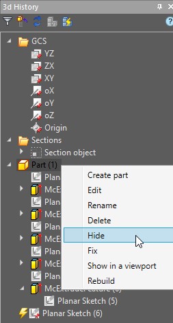
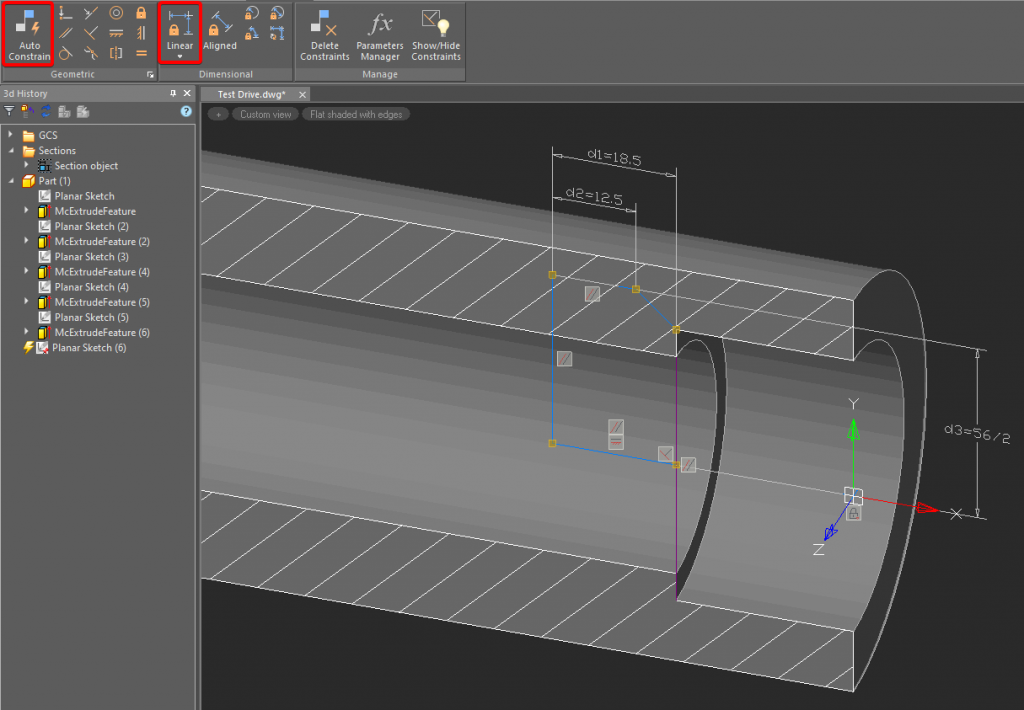
4. When done, apply the Auto Constraint to ease line selection. You can hide the whole part: just right-click the part’s name in the 3D history and choose Hide. If you want to make it visible again, right-click the part’s name and choose the Show option. After the Constraint is done, use the Linear command in the Dimensional group (Fig. 16).
The fillets are also shown in the drawing. We can create them either in the sketch with the Fillet command on the Draw tab, or with the 3D Fillet command by clicking the Fillet Edge button (see «3D Fillets and Chamfers»).
5. Switch to the 3D Tools tab and click Revolve. Select the sketch area. In the dialog box click TgSolid and choose Part (1) in 3D History. In the 3D Revolve dialog box choose the Cut option and select Axis. Specify the rotation axis and click OK (Fig. 17).
6. Construct the ⌀61, ⌀47, ⌀56 diameters by using the reference drawing. You can implement any of the methods described above. The final sketch created with the 3D Revolve operation is shown in Fig. 18.
2. Zoom in the previous construction and project the inner end plane of the hole. Use the Add Projection command in the 2D Sketch group. If needed, you can switch to an isometric view with Shift + mouse wheel (Fig. 15).

Fig. 15 Projecting an element onto the 2D sketch
The projected face (edge) will appear as a line. We will use this line for future 3D model constructions.
3. Design the contour of the future hole with a snap without specifying the segment dimensions. The construction should start from the projected line. The end point should be defined with the Midpoint snap. Press Shift for the orthogonal drawing.
4. When done, apply the Auto Constraint to ease line selection. You can hide the whole part: just right-click the part’s name in the 3D history and choose Hide. If you want to make it visible again, right-click the part’s name and choose the Show option. After the Constraint is done, use the Linear command in the Dimensional group (Fig. 16).
The fillets are also shown in the drawing. We can create them either in the sketch with the Fillet command on the Draw tab, or with the 3D Fillet command by clicking the Fillet Edge button (see «3D Fillets and Chamfers»).


Fig. 16. The sketch with the parametric constraints
5. Switch to the 3D Tools tab and click Revolve. Select the sketch area. In the dialog box click TgSolid and choose Part (1) in 3D History. In the 3D Revolve dialog box choose the Cut option and select Axis. Specify the rotation axis and click OK (Fig. 17).

Fig. 17. The 3D Revolve operation
6. Construct the ⌀61, ⌀47, ⌀56 diameters by using the reference drawing. You can implement any of the methods described above. The final sketch created with the 3D Revolve operation is shown in Fig. 18.

Fig. 18. The sketch with the 3D Revolve operation


 De
De  Es
Es  Fr
Fr  Pt
Pt 
