nanoCAD 3D Solid Modeling Module
3D Extrude Operation
1. Click the 3D Extrude command on the 3D Tools tab (Fig. 7). Move the cursor to the circle area and confirm the sketch selection with the left-click (LMB).

Fig. 7. The 3D Extrude operation
2. In the 3D Extrude dialog box, enter the distance value 255 and click the Negative Direction button. Confirm with OK (Fig. 8).

Fig. 8. The dialog box of the 3D Extrude operation
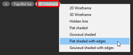
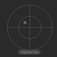
Switch the view orientation to Top NW Isometric using the Locator for your convenience. Then, switch the visual style to Flat shaded with edges (Fig. 9).


Fig. 9. Switching views and visual styles
4. Let’s design a sketch on the front end of the object. On the 3D Tools tab, click Add Sketch command (Fig. 10) and press LMB to select the front end of the 3D model. The system has switched to sketch mode. Draw a circle with a ⌀95 diameter.

Fig. 10. Add Sketch command on the 3D Tools tab
Once again, activate the 3D Extrude operation on the 3D Tools tab. Choose the sketch area between the big and small circles with a click. In the window that has appeared, activate the Сut option (Fig. 11). In the Distance field enter 255-20 and choose the Negative control direction. Click OK to confirm the operation.

Fig. 11. Option cut of the 3D extrude operation
5. Similar to the previous step, construct a surface with ⌀75 diameter and 165 long.
6. Construct a hole with ⌀36 diameter. Select the Through option in the pop-up menu in the parameters of the 3D Extrude operation.
7. Draw a hole with ⌀45 diameter for the M48x2 thread. Type 45-18.5 in the Distance field.
The result is shown in Fig. 12.

Fig. 12. The result of construction using the 3D Extrude operation
The next element will be designed with the 3D Revolve operation. But first, let's generate a section.


 De
De  Es
Es  Fr
Fr  Pt
Pt 
