
 De
De  Es
Es  Fr
Fr  Pt
Pt 

Creating Parametric Objects in nanoCAD Mechanica Part 1
nanoCAD Mechanica has a library of standard parts. Most elements of the library are parametric objects related to each other by certain dependencies. These dependencies are defined by the standards of the elements.
A parametric object is an element with a geometry controlled via parameters.
The MechWizard module in nanoCAD Mechanica helps you create objects with parameters connected by certain dependencies not only within the object, but also with the parameters of other library objects. This allows you to generate different variations or types of the same object by using different parameters, as well as manage multicomponent assemblies, creating different variations of a single node or a part as a whole.
In this article we will review some examples of the parameterization module’s capabilities in nanoCAD Mechanica. This short tutorial will teach you how to create parametric elements.
To create a parametric part with standard nanoCAD tools, draw a simple geometric object consisting of primitives. You can also import it in *.dwg format from another software (Figure 1).
When drawing a hatch select Type — User defined. You will need this later for parametric geometry recognition while creating a library object (Figure 2).
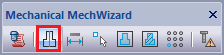
To display the hatching correctly, you should set a thin linetype (Linetype: 2). To set the line type, select Mechanica — Standard parts — MechWizard — Set parameter from a drop down menu. You can also run this command by clicking on the corresponding button on the MechWizard toolbar (Figure 3).
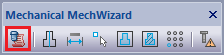
For convenience, we recommend using the Mechanical MechWizard toolbar to work with ScriptMaster. To display the toolbar, select the View menu and go to Toolbars — Mechanica — Mechanical MechWizard (Figure 4).
Let's draw the second view and assign dimensions. Use the Latin alphabet for all dimensions. It is important to use the same symbols for all dimensions on different views of the same geometric elements. (Figure 5).
The l parameter in the first view is required to create an insertion point. To define this point, let’s create an additional line segment and set a parameter for it. Call the menu Mechanica – Standard parts – MechWizard – Set parameter (or click the corresponding button on the MechWizard toolbar), select the segment and press Enter. In the Object Properties window that opens, enable the Is a working Object option and click OK (Figure 6).
Both views are now ready. First, create a symmetric axis for the views by selecting the Symmetry axis tool in the MechWizard toolbar and choosing the center lines for both views.
After creating the element geometry and setting defining dimensions create an object in the library of parts. Call the SriptMaster via the menu Mechanica – Standard parts – MechWizard – ScriptMaster or by clicking the ScriptMaster button on the Mechanical MechWizard toolbar.
In the MechWizard window select New Object from the menu or click New Object. In the New Object window, select the library folder where you want to save the object (in this case, User Folders), fill in the Name field, and click OK (Figure 7).
The object is created. Let’s add geometry now. In the MechWizard, right-click on the Implementation branch and select Add implementation from the context menu. Then, right-click in the Wizard's workspace to create another view (Figure 8).
Let's label the first view as the Front View. Select it and click on the corresponding View display button. Then, label the second view as the Side View (Fig. 9).
Now let’s assign the corresponding geometry to the views created in the MechWizard. Right-click on the view and select Parametric recognize view from the context menu. The system will switch to Model mode. Select the object and choose Enter in the context menu or press Enter on the keyboard (Figure 10).
To complete the operation, select an insertion point (the left edge of the l segment). If recognition is successful, a corresponding message will appear (see Figure 11).
Perform the same actions for the side view. Select the center of the object's coordinate axes as an insertion point (Figure 12).
We have seen how you can create a library object and define geometry for it by using the MechWizard in nanoCAD Mechanica.
In the next part, we will take a look at how you can parameterize this object with the ScriptMaster, as well as by using an object-analogue
A parametric object is an element with a geometry controlled via parameters.
The MechWizard module in nanoCAD Mechanica helps you create objects with parameters connected by certain dependencies not only within the object, but also with the parameters of other library objects. This allows you to generate different variations or types of the same object by using different parameters, as well as manage multicomponent assemblies, creating different variations of a single node or a part as a whole.
In this article we will review some examples of the parameterization module’s capabilities in nanoCAD Mechanica. This short tutorial will teach you how to create parametric elements.
Part 1. Preparing the object's geometry. Creating a library element.
To create a parametric part with standard nanoCAD tools, draw a simple geometric object consisting of primitives. You can also import it in *.dwg format from another software (Figure 1).
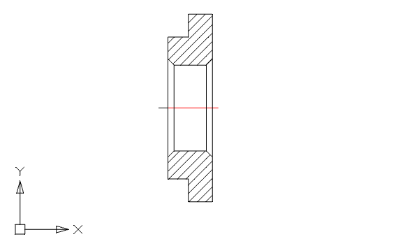
Fig. 1
When drawing a hatch select Type — User defined. You will need this later for parametric geometry recognition while creating a library object (Figure 2).
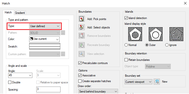
Fig. 2
To display the hatching correctly, you should set a thin linetype (Linetype: 2). To set the line type, select Mechanica — Standard parts — MechWizard — Set parameter from a drop down menu. You can also run this command by clicking on the corresponding button on the MechWizard toolbar (Figure 3).
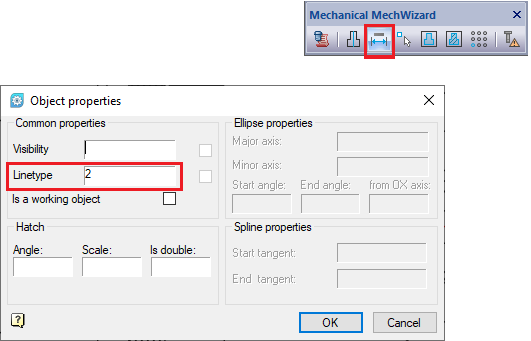
Fig. 3
For convenience, we recommend using the Mechanical MechWizard toolbar to work with ScriptMaster. To display the toolbar, select the View menu and go to Toolbars — Mechanica — Mechanical MechWizard (Figure 4).
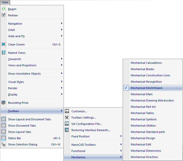
Fig. 4
Let's draw the second view and assign dimensions. Use the Latin alphabet for all dimensions. It is important to use the same symbols for all dimensions on different views of the same geometric elements. (Figure 5).
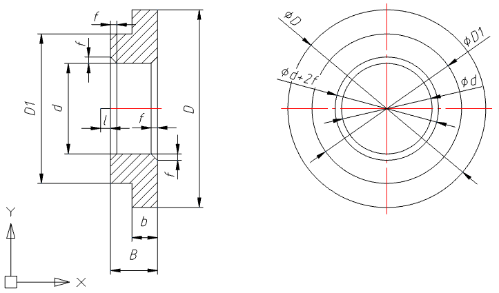
Fig. 5
The l parameter in the first view is required to create an insertion point. To define this point, let’s create an additional line segment and set a parameter for it. Call the menu Mechanica – Standard parts – MechWizard – Set parameter (or click the corresponding button on the MechWizard toolbar), select the segment and press Enter. In the Object Properties window that opens, enable the Is a working Object option and click OK (Figure 6).
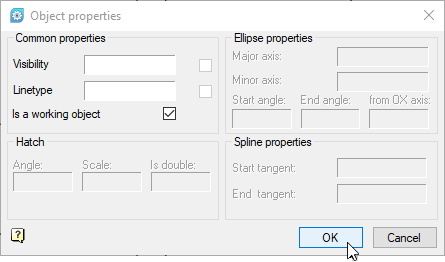
Fig. 6
Both views are now ready. First, create a symmetric axis for the views by selecting the Symmetry axis tool in the MechWizard toolbar and choosing the center lines for both views.
After creating the element geometry and setting defining dimensions create an object in the library of parts. Call the SriptMaster via the menu Mechanica – Standard parts – MechWizard – ScriptMaster or by clicking the ScriptMaster button on the Mechanical MechWizard toolbar.
In the MechWizard window select New Object from the menu or click New Object. In the New Object window, select the library folder where you want to save the object (in this case, User Folders), fill in the Name field, and click OK (Figure 7).
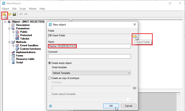
Fig. 7
The object is created. Let’s add geometry now. In the MechWizard, right-click on the Implementation branch and select Add implementation from the context menu. Then, right-click in the Wizard's workspace to create another view (Figure 8).
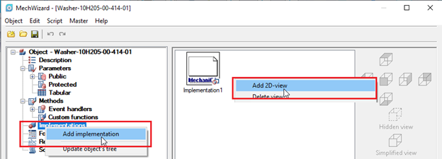
Fig. 8
Let's label the first view as the Front View. Select it and click on the corresponding View display button. Then, label the second view as the Side View (Fig. 9).
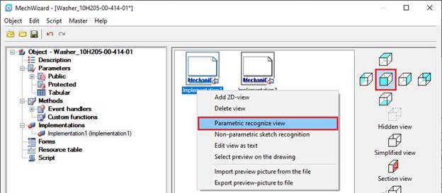
Fig. 9
Now let’s assign the corresponding geometry to the views created in the MechWizard. Right-click on the view and select Parametric recognize view from the context menu. The system will switch to Model mode. Select the object and choose Enter in the context menu or press Enter on the keyboard (Figure 10).
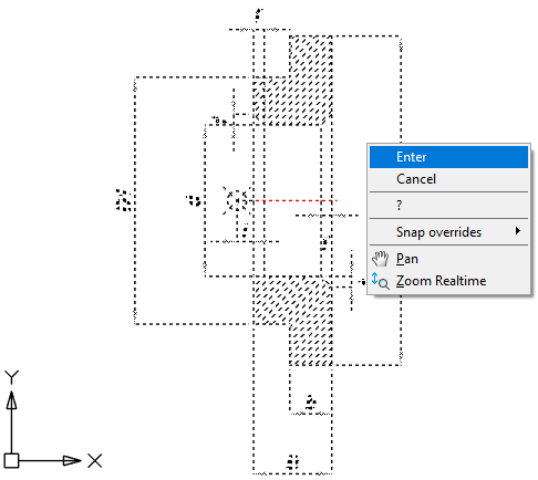
Fig. 10
To complete the operation, select an insertion point (the left edge of the l segment). If recognition is successful, a corresponding message will appear (see Figure 11).
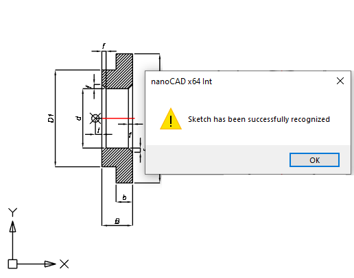
Fig. 11
Perform the same actions for the side view. Select the center of the object's coordinate axes as an insertion point (Figure 12).
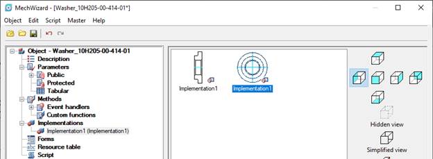
Fig. 12
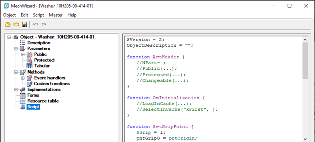
Fig. 13
We have seen how you can create a library object and define geometry for it by using the MechWizard in nanoCAD Mechanica.
In the next part, we will take a look at how you can parameterize this object with the ScriptMaster, as well as by using an object-analogue